Week 9 - Attachment Feature Creation - Challenge 2
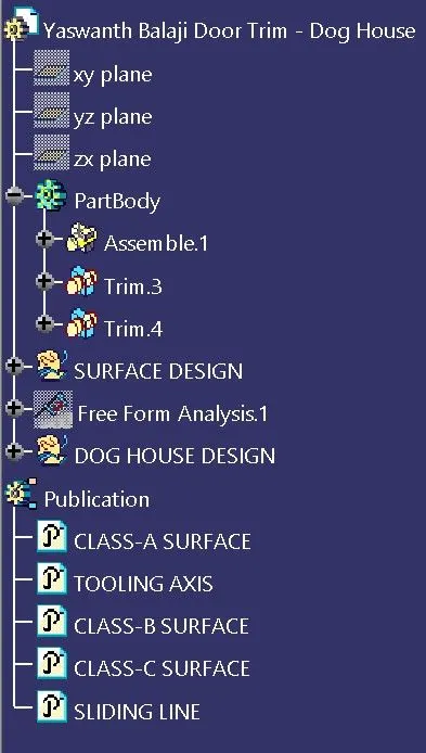
STRUCTURE TREE
SKETCHES
- POSITIONED SKETCH
SKETCH-1
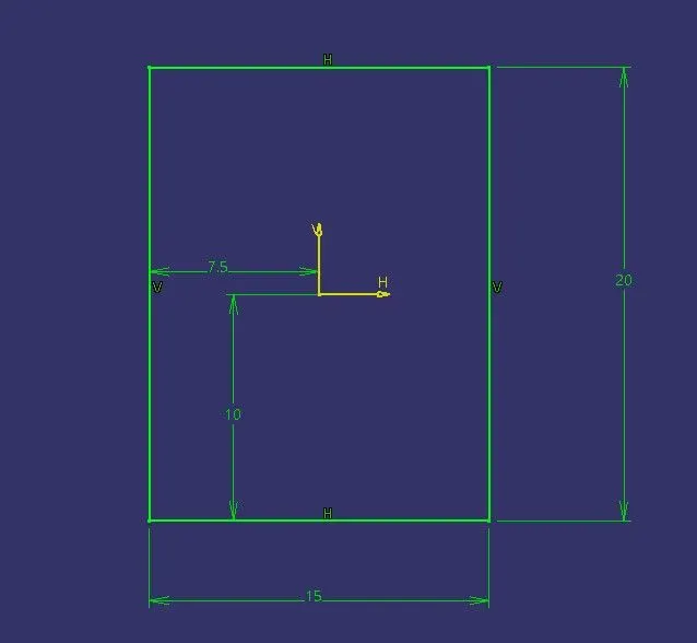
SKETCH-2
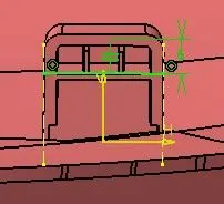
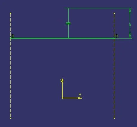
SKETCH-3
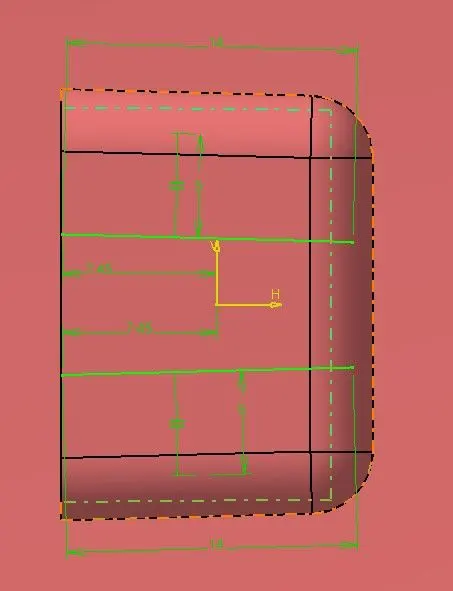
SKETCH-4
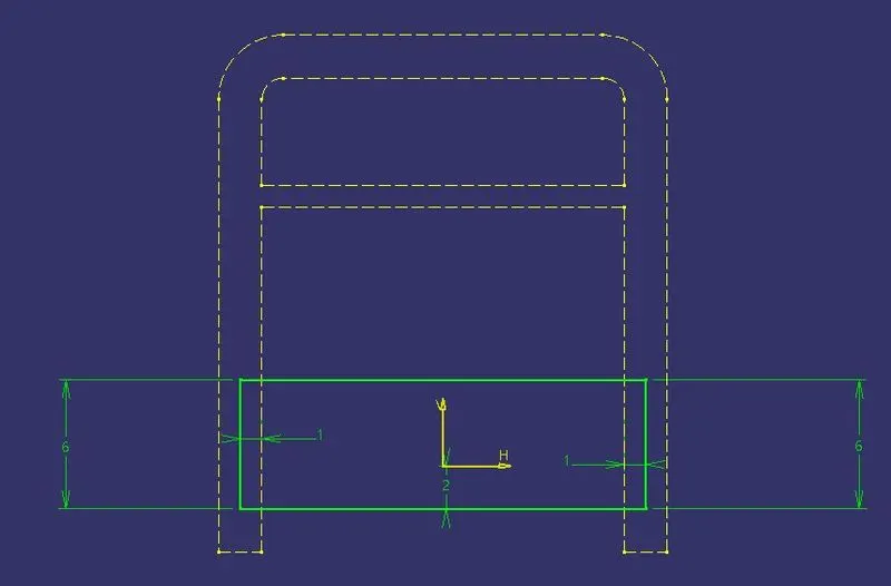
- ISO-CONSTRAINED SKETCH
SKETCH-1
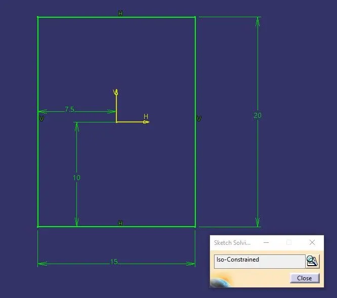
SKETCH-2
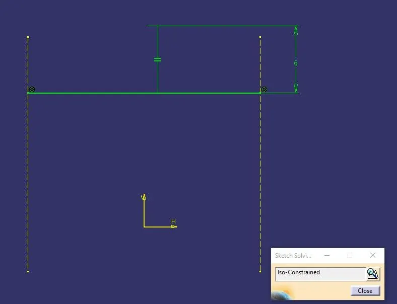
SKETCH-3
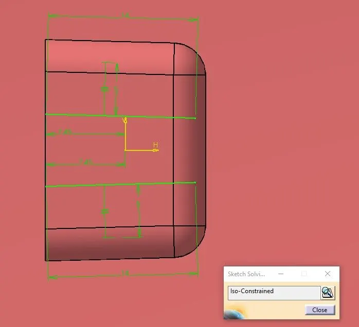
SKETCH-4
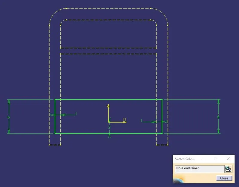
*NOTE:
- The dimensions were given as a reference from technical engineers as they were not mentioned in the challenge guidelines.
3-D IMAGES:
INPUT/CLASS-A SURFACE
- ISOMETRIC VIEW
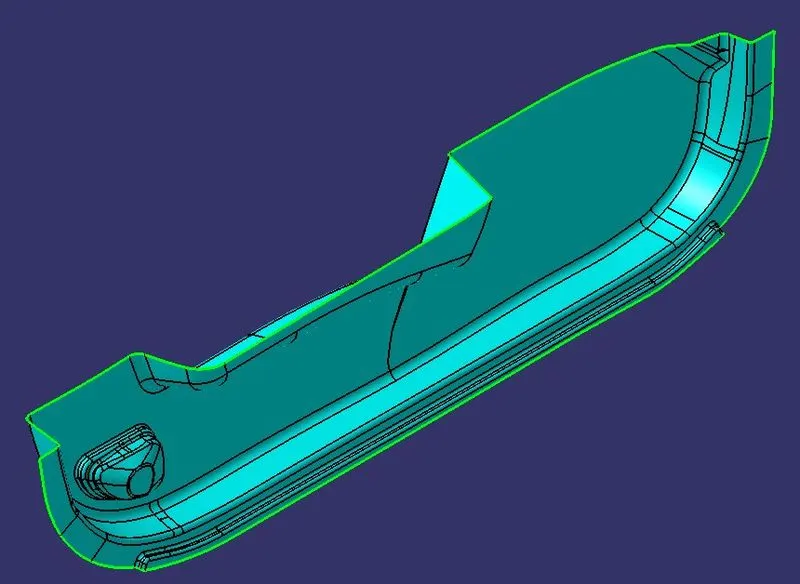
- FRONT VIEW
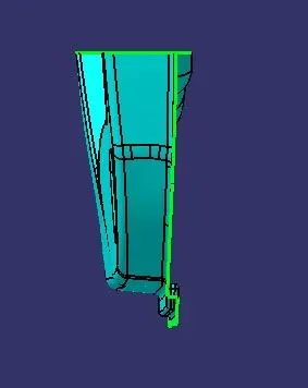
- RIGHT-SIDE VIEW
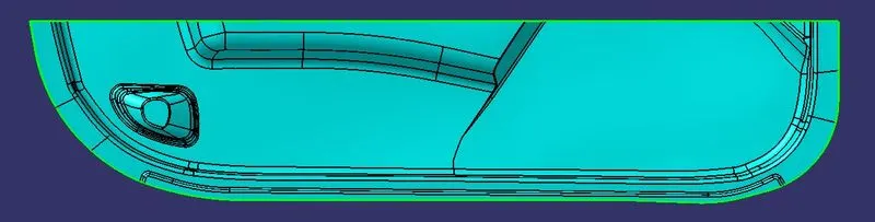
- TOP VIEW

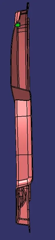
FINAL ASSEMBLY COMPONENT
- ISOMETRIC VIEW
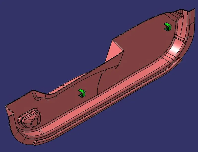
- FRONT VIEW
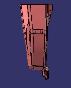
- RIGHT-SIDE VIEW
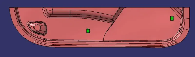
- TOP VIEW
DOG HOUSE in ASSEMBLY
- ISOMETRIC VIEW
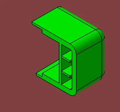
- FRONT VIEW
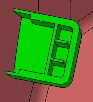
- RIGHT-SIDE VIEW
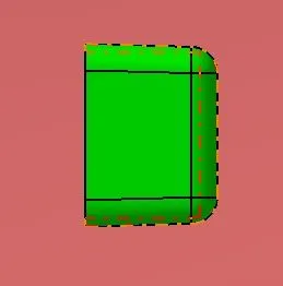
- TOP VIEW
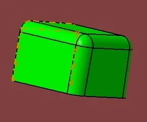
DRAFT ANALYSIS:
INPUT/CLASS-A SURFACE
- ISOMETRIC VIEW

- FRONT VIEW
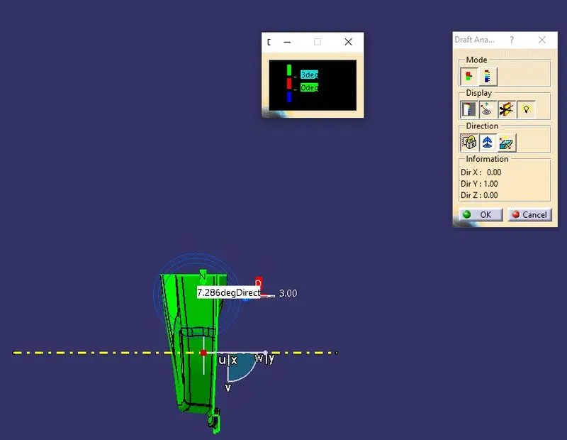
- RIGHT-SIDE VIEW
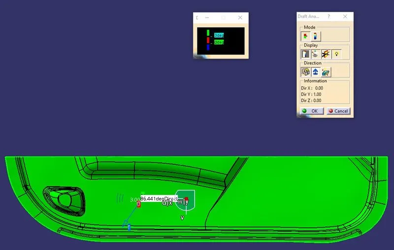
- TOP VIEW

FINAL ASSEMBLY COMPONENT
- ISOMETRIC VIEW
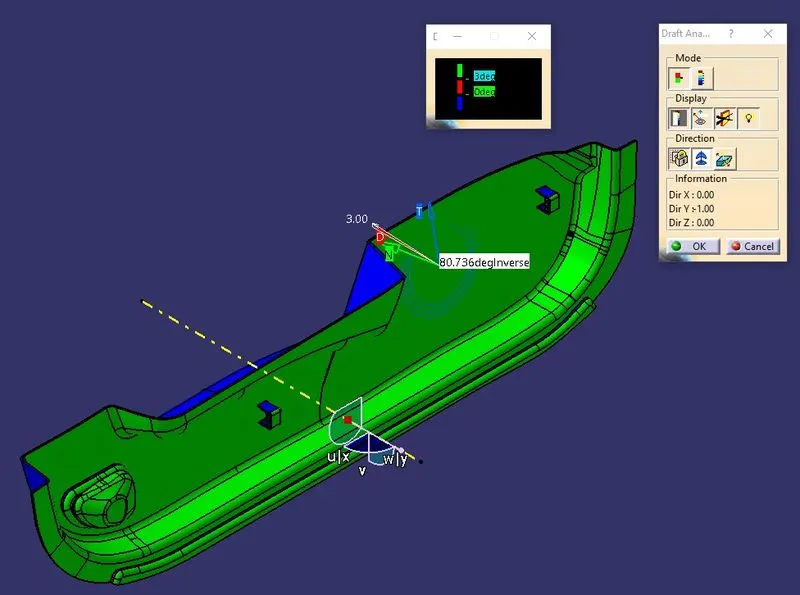
- FRONT VIEW
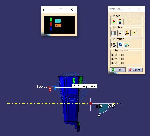
- RIGHT-SIDE VIEW
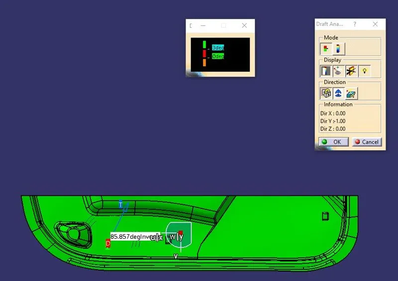
- TOP VIEW
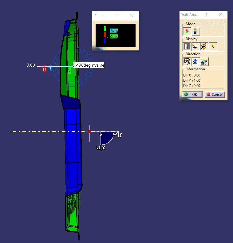
DOG-HOUSE
- ISOMETRIC VIEW
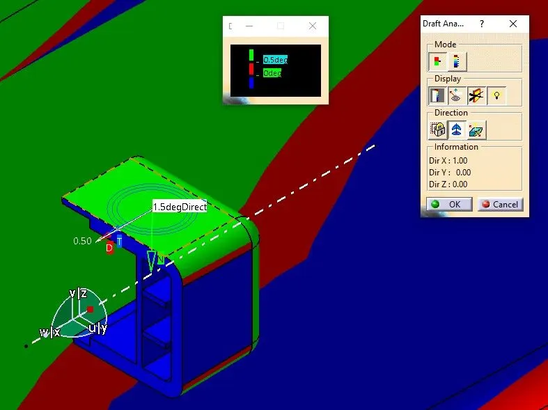
- FRONT VIEW
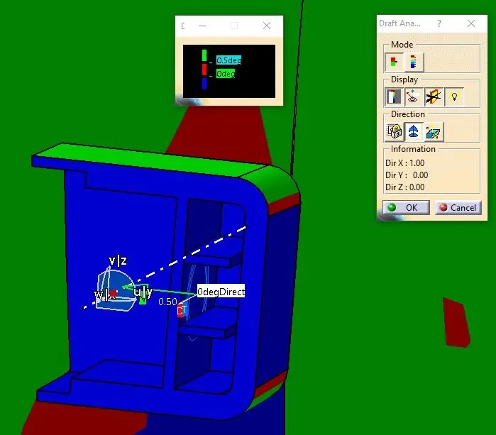
- RIGHT-SIDE VIEW
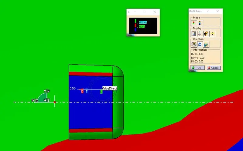
- TOP VIEW
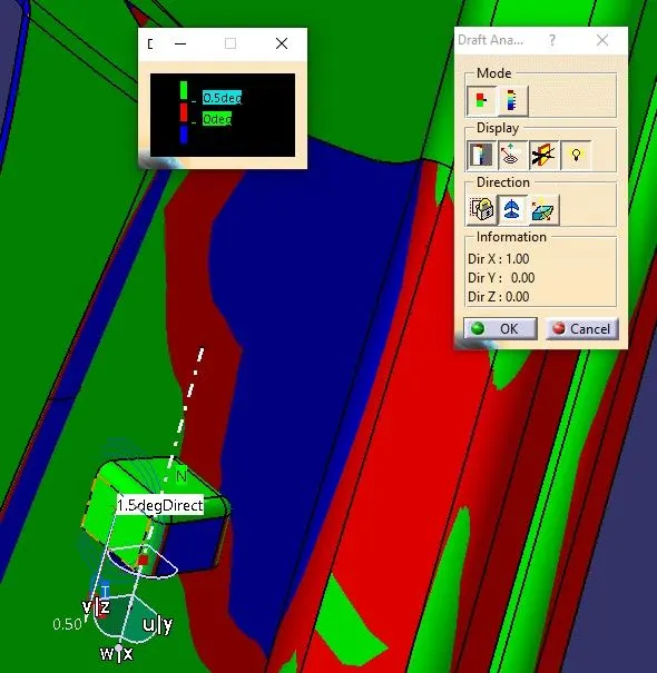
*NOTE:
- There are errors in the draft analysis due software version issues.
REPORT:
1. TOOLING AXIS
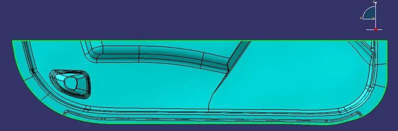
- By changing the view on the aixs we can see in which axis-view the CLASS-A is seen clearly.In this case,the y-axis is the best view possible to see the component clearly.
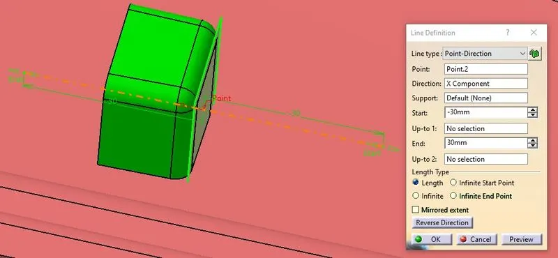
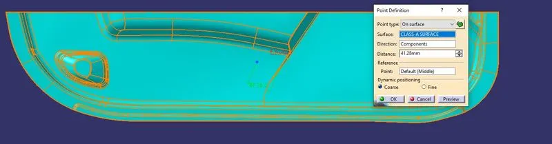
- Pick the POINT on the surface of CLASS-A surface.
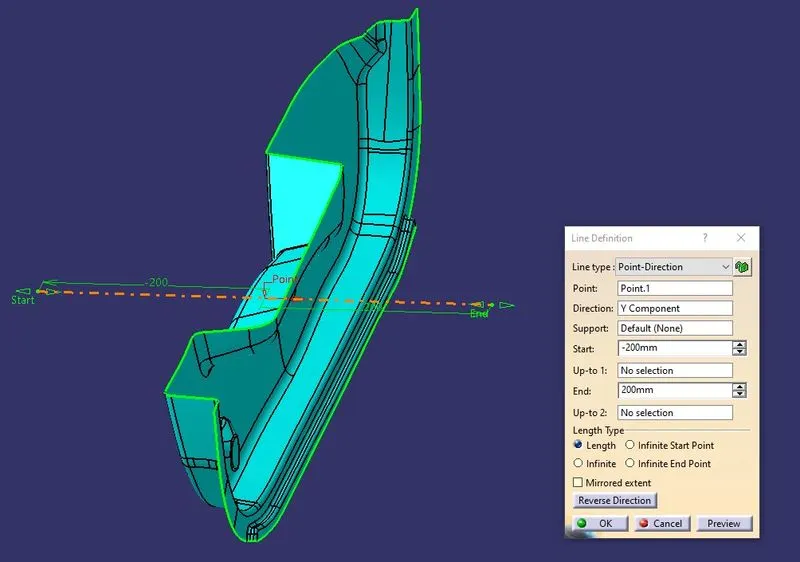
- Create a line using the POINT in the view direction with the desired lenght which will be the TOOLING AXIS of the component.
2. SLIDING AXIS
- Create an EXTRACT on the back of the Dog House surface.
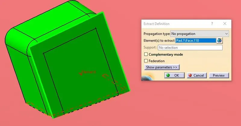
- Pick a POINT on the centre of the surface.
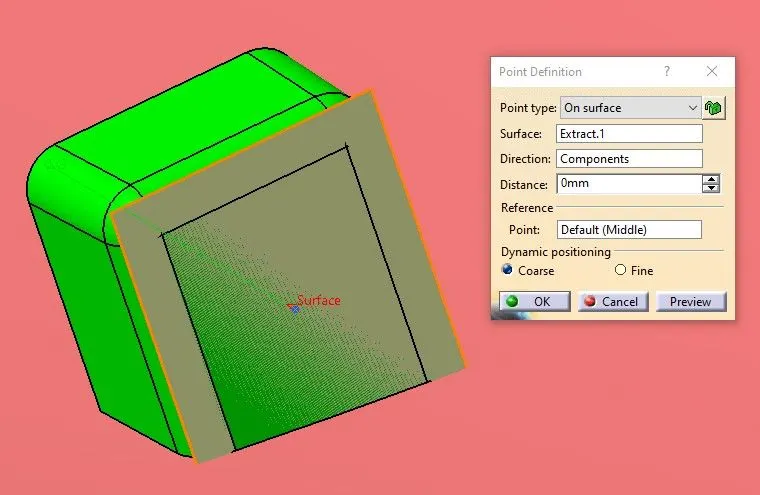
- Create a line perpendicular to the surface of the extract in the desired lenght called as SLIDING ANGLE which is a different draft angle to the Dog House compared to the Assembly Component.