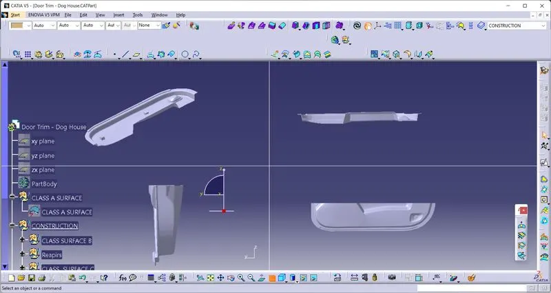
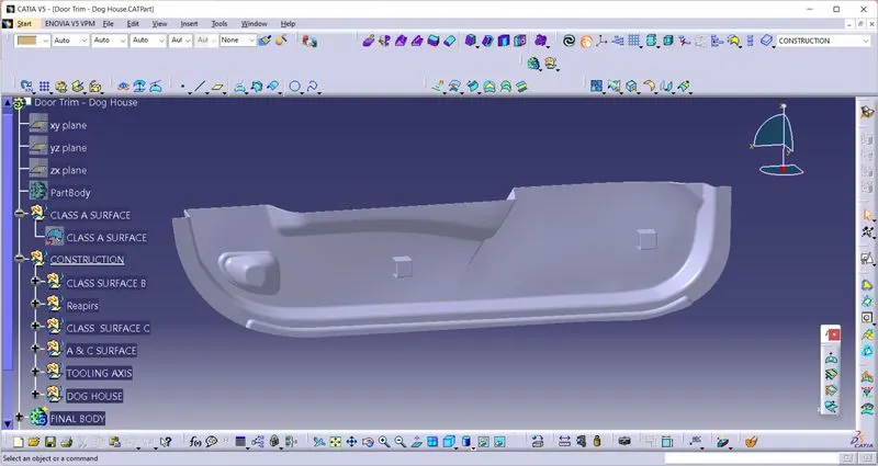
Week 9 - Attachment Feature Creation - Challenge 2
AIM- Create the screw boss and dog house for the centre console coin holder considering the design rules mentioned in the video.
Class A Surface-
Class A Surface is the asthetic sutface that is created through scaning of clay model. This Class a Surface is a input CAD model for part design.
Class B surface-
Class B surface is created in a certain distance according to the thickness of the part. Class B Surface contain all engineering compoonent.
Class C Surface-
Class c Surface joins the Class A & Class B Surfaces.
C is where the doghouse contacts the back side of the surface
NOW DOG HOUSE DESIGN
-
Doghouse wall thickness at the intersection of the part wall ( C ) should be 40% or less than the main wall stock ( T ).
-
The height of ( B ) should be between 3.0 – 6.0 mm
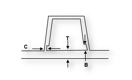
"C" is where the doghouse contacts the backside of the surface
CREATING DOG HOUSE:
Create a sketch on the extracted base surface where the the dimensions should be more than the screw boss As for the Dog house one of the sides should be opened,make one side as a construction line.
Extrude the sketch by using the Sweep option with the 1.5 degrees to the height of 20mm towards top and 1mm towards bottom.
To cover the top surface,offset the extracted base surface to a distance of 20mm and then trim it and fillet the edges with 1mm.Pad the extruded surface to outside with the thickness of 2mm.
.Cut the uneven surface at the open side by extracting the opposite surface and offset it to a distance towards the open surface and split the part in Part design by using the Split option.
Draft the inner walls with 0.5 degrees.Now create backside contact surface by offsetting the extracted base surface to a distance in between 3 - 6mm height (B) and Sweeped surface to a distance of 40% of the main wall thickness(C).Trim the surface.
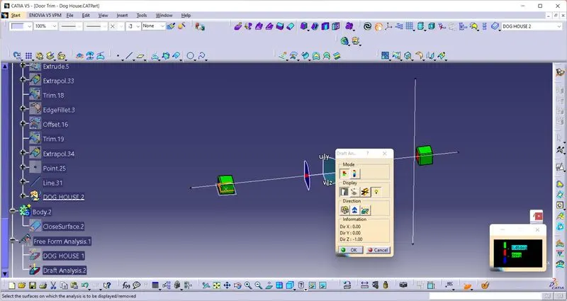
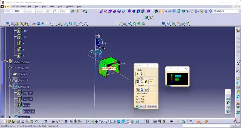
CREATING TOOLING AXIS:
2.Create a point at the center of the base by using Point Definition by extracting the surface and selecting the surface.
3.Create an Axis system at the point that is created at the surface using Axis System Definition by selecting the point.
4.Now create an intersection in the ZY plane by Intersection Definition for the Center
5.Now using Point-Point in Point Definition extend the line to take reference drafted lines on both sides and bisect those lines to get the direction in the ZY plane.
6.Create an intersection in the ZX plane and create a Tooling axis in the ZX plane.
7.Bisect those two tooling axis lines and create a Main Tooling axis