Week 9 - Attachment Feature Creation - Challenge 2
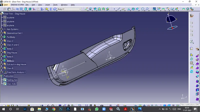
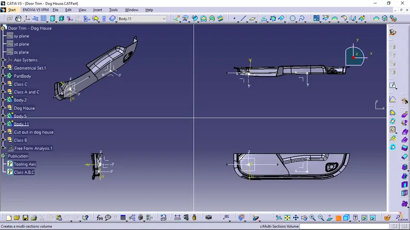
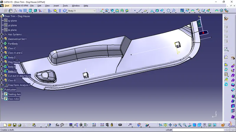
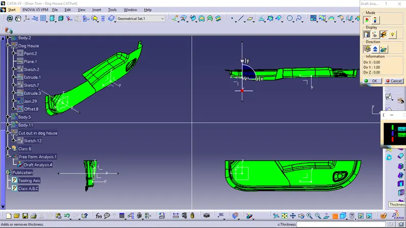
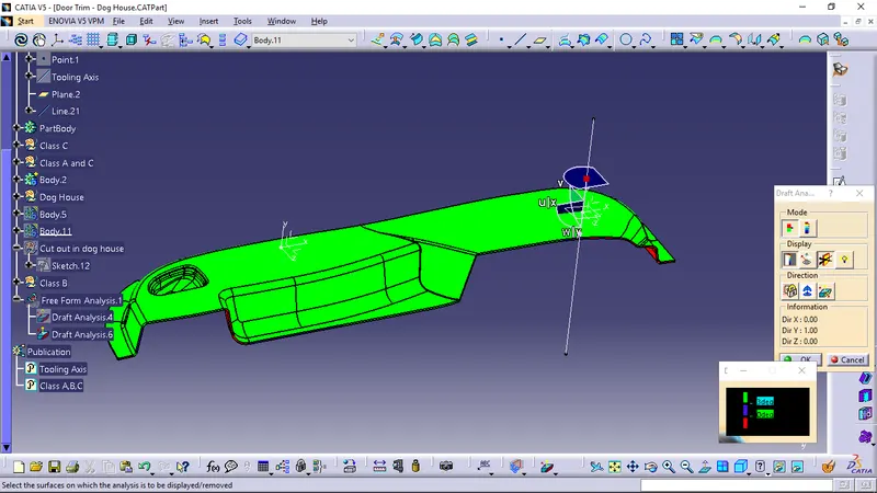
Draft Analysis 1 On Class A Surface
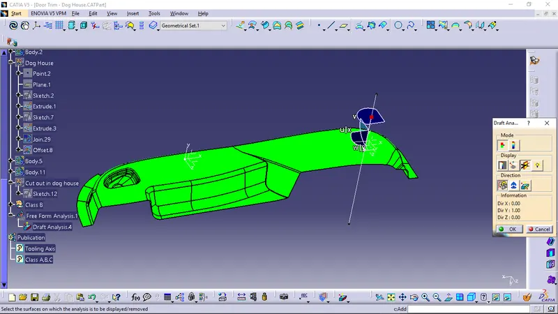
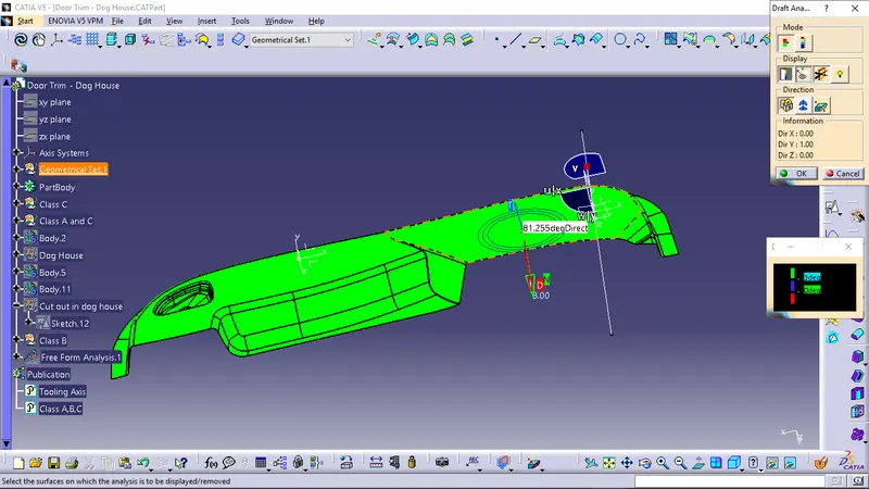
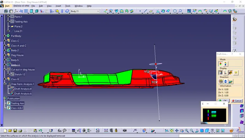
Draft Analysis 2 on Class A,B,C
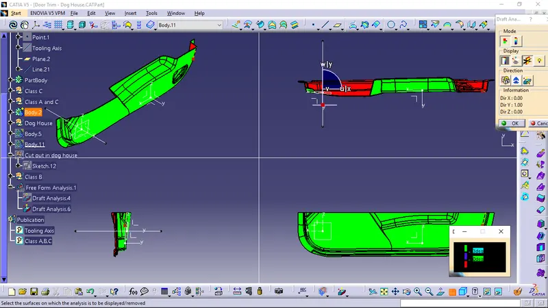
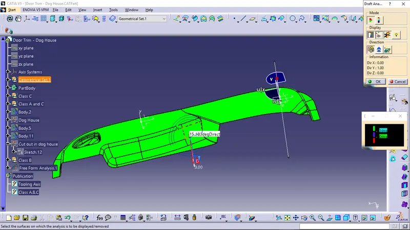
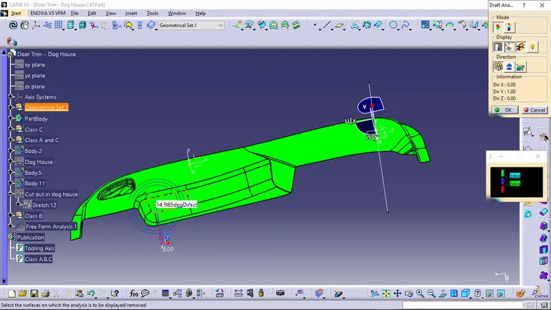
Draft Analysis 3 on Dog house
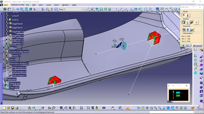
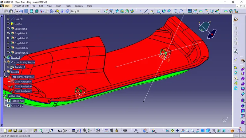
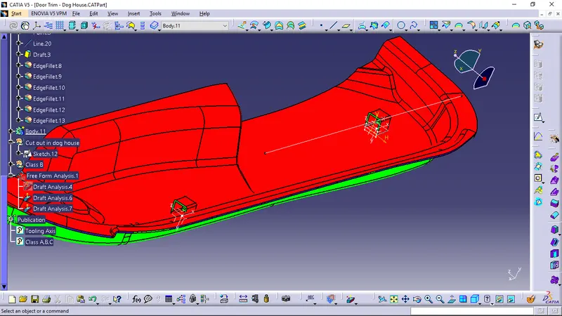
1] First thing which we did is to have a center point which will be convenient for further analysis, here We have taken the center point on the surface which can be seen in the picture.
2] Then the by drawing a line using point-direction relation tooling axis is created.
This is the way Tooling axis is created.
As we can see the draft analysis 1 shows complete green colour.
Here colours show the ejectability by stating whether the draft angle is right or wrong.
Green = Draft value above 3 deg
Red = Below 0deg
Blue = 0-3 deg
Draft Analysis 1
As we know first analysis is performed on the class A surface which is green , it shows the ejectability by the analysis.
Here we can also see a very small patches of red colour which indicates irregularity of the surface.
Draft Analysis 2
But the second analysis where class A, class B, class C all these surfaces are involved .
In these analysis we can see green and red colour as well.
As here we have taken C suface with reference to the surface,It shows discontinutity in colour
Drfat Analysis 3
Here we can see It has mostly red colour as it has no assosiation with class A surface.
Also we have created the new axis system for dog houses.
Irregularities in the analysis shows that we need to change some things in the design.