Week -2
1]
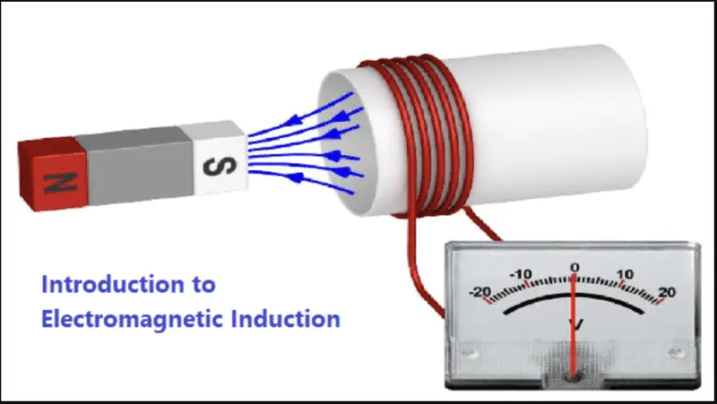
This image shows the faraday's law of electromagnetic induction
It is the basic law of electromagnetic induction predicting how a magnetic field will interact with an electric circuit to produce an electromotive force(emf).
In the file attached with the report called 'Doorbell' as we can see, the circuit is made up of components -:
1] Pulse generator
2] Switch
3] Battery
4] Solenoid
5] Ideal translational motion sensor
6] Electrical reference
7] Solver configuration
8] Simulink-PS Converter
9] PS-Simulink Converter
1]
Here we are giving the input in the form of pulse generator, as it is mentioned in the question that the switch is closed for 2 seconds,
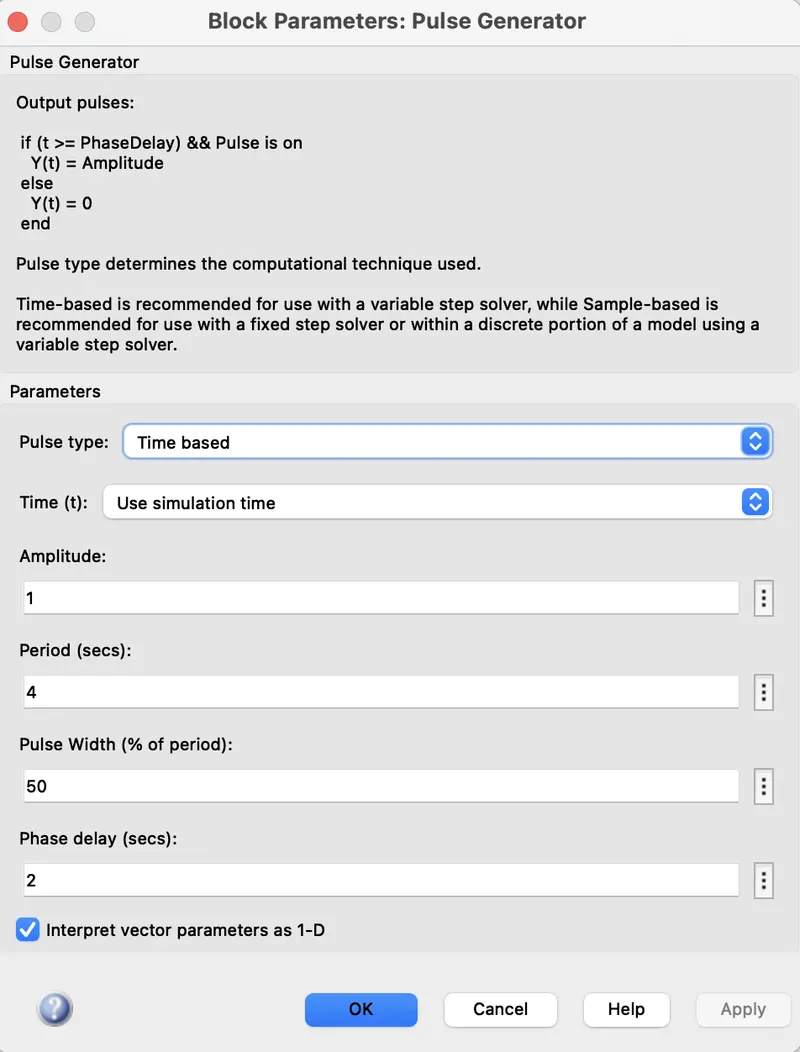
This how input signal configuration is set, where switch is closed for 2 seconds.
2]
This signal is converted in to physical signal by using simulink to physical system converter whose one end is connected to battery and another end is connected to the solenoid. Here we have given electrical reference to complete the circuit or to avoid any short circuit situation.
3]
A solenoid is a type of electromagnet formed by a helical coil of wire whose length is substantially greater than its diameter,which generates a controlled magnetic field.
4]
So, now when the switch is closed the electromagnet(Solenoid) receives the electrical power from the battery and pulls the metal arm to hit the bell producing sound.
Here we have used Ideal translational motion sensor as it takes electrical input and converts it into mechanical translational motion to pull the metal arm.
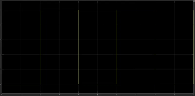
Input signal for doorbell circuit
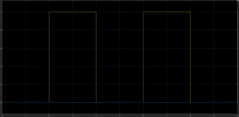
Output signalfor doorbell circuit
2]
Thermistor is a device discovered by Michael Faraday in 1833.
A thermistor is a semiconductor that has a resistance capacity more than a conducting material and less insulating material.
Components used-:
1] Signal Buider
2] Simulink-PS converter
3] Controlled Temperature Source
4] Thermistor
5] Voltage sensor
6] Battery
7] Solver configuration
8] Electrical reference
9] PS-Simulink converter
10] Switch
11] Controlled voltage source
12] DC motor
13] Ideal rotational motion sensor
14] Scope
1]
Here we are starting with giving the signal from signal builder according to the given condition(Input signal).
To convert this signal in the physical system we are using simulink-PS converter.
2]
It is further connected to the controlled temperature source.
This block represents an ideal energy source in a thermal network that can maintain a controlled temperature difference regardless of the heat flow rate.
The temperature signal is set by the physical signal port S.
3]
Furthermore, this controlled temperature source is connected to thermistor which is explained earlier.
Thermistor's electrical resistance varies with the change in the temperature and thermally sensitive resistor.
There are mainly two types of thermistors-:
1)Negatuve temperature coefficient(NTC)
2)Positive temperature coefficient(PTC)
NTC thermistor is calculated using formula-:
R0 = R0(1 + alpha(T - T0))
The temperature of the thermistor is governed by equation,
m*c*dT/dt = Q.
4]
Then we use the voltage sensor for converting temperature in terms of electrical quantity which is connected to the switch where threshold is set up to a certain point.
Only when the voltage is beyond a certain threshold which is set. The fan will get switched on.
Further there is set up of fan which includes Controlled voltage source, DC motor, Ideal Rotational motion sensor.
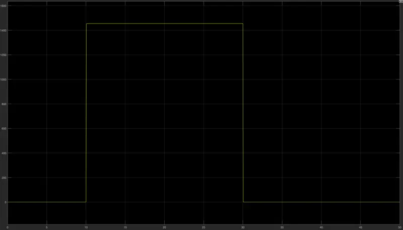
Above image depicts the output of Thermistor circuit.