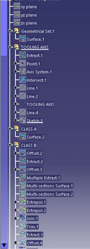
To create the Geomatry set with proper name and sub geomatry set also.
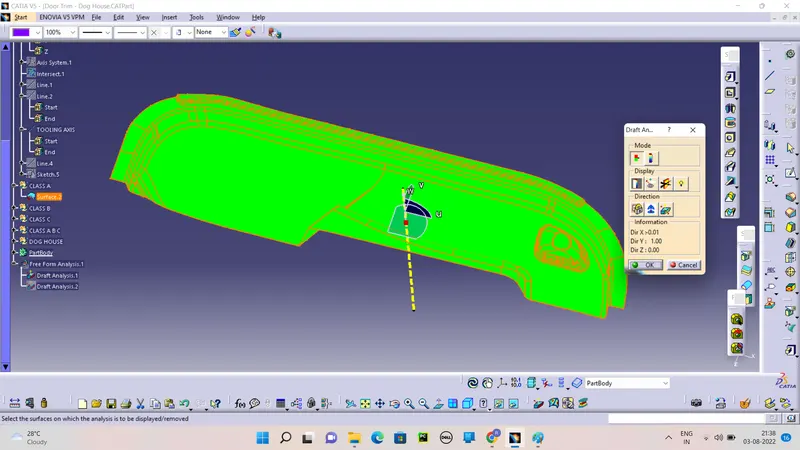
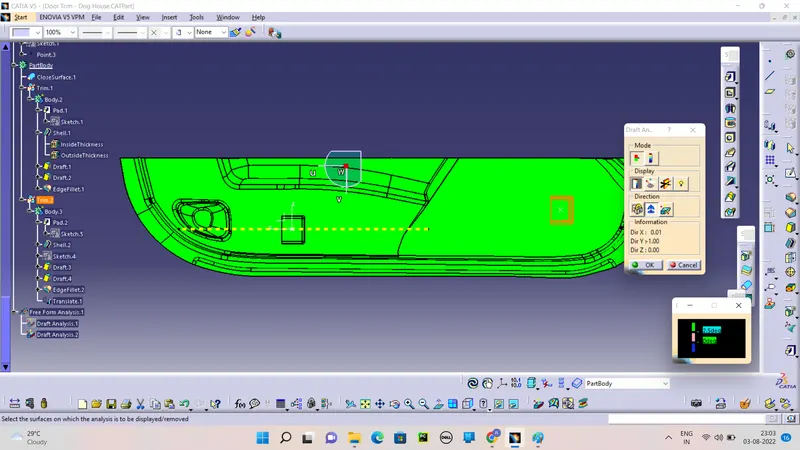
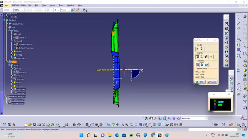
A positive draft means the angle of the face, with respect to the direction of pull, is more than the reference angle. Negative draft. Displays any faces with a negative draft, based on the reference draft angle you specified.
Dog house is an engineering feature used in plastic trim design. Dog houses are used as supporting feature. Sometimes other engineering features like snaps; locators etc. are mounded on them to increase their strength.
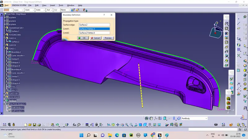
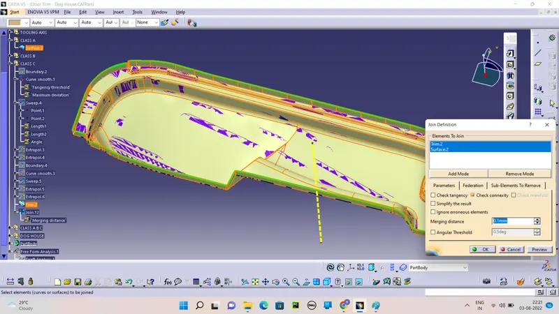
The direction in which the mold or core and cavity opens is the tooling axis. Connectivity of Class-A surface: Checking the connectivity of the surface, this can be done by creating boundaries or by simply using the join option such that any openings can be easily visualized.
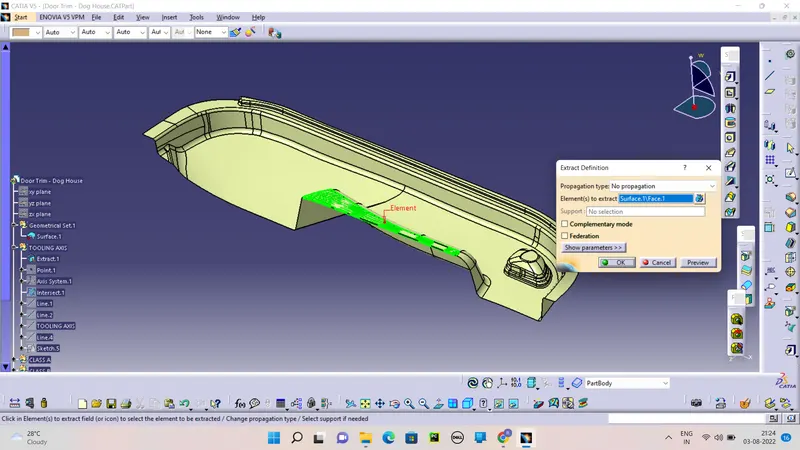
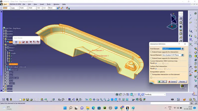
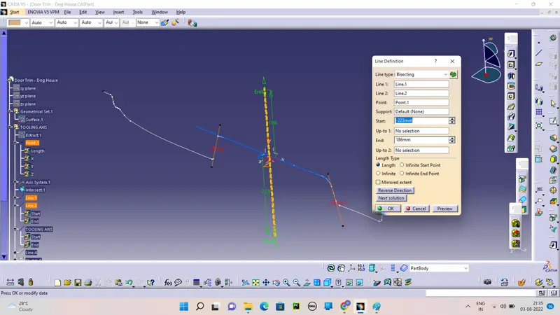
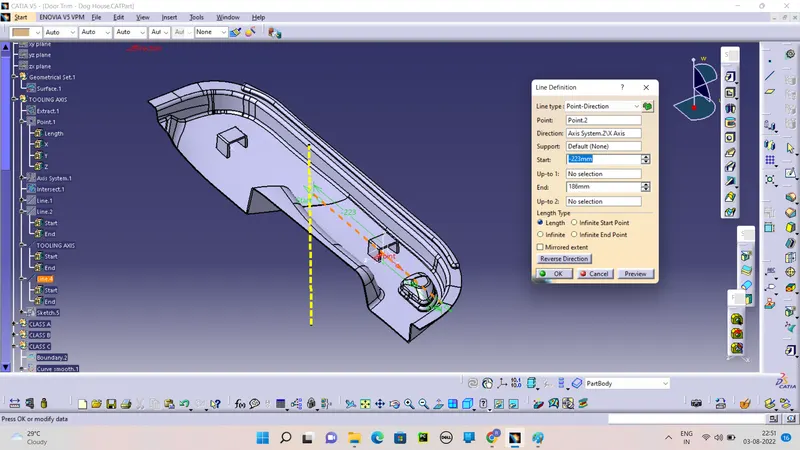
Create the Toolig Axis by the Bisection Line Command. First create the intersection of the Surface A and we get the line.
Draw the line on the Intersection curve extrant it. By the help of two line Draw the Tooling Axis.
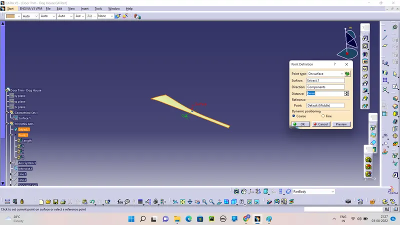
Create the Axis systen on the point and intersection with surface.
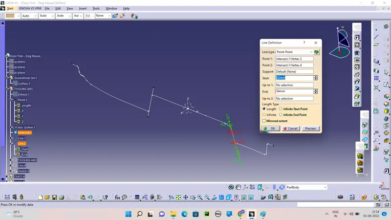
Create the Two line and then create the Tooling axis from the line by the Bisecting line.
Creating Tooling Axis.
CREATE THE CLASS A WITH DRAFT ANGLE:
Draft angle (the degree of taper of the side wall of the mold or the angle of clearance designed to aid removal of a part from a mold) increase causes a linear decrease of the force required to remove a molded object from a mold.
CREATE CLASS B:
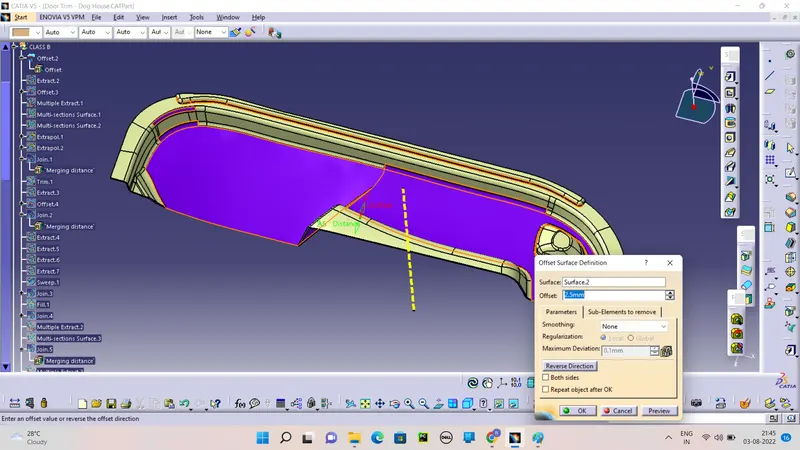
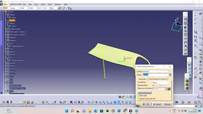
Just Offset of the class A surface to 2.5mm.
They are some missing patch and surface. so we create first missing surface.
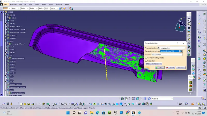
First create the big missing surface by the Extract from Class A and Offset it to 2.5 mm.
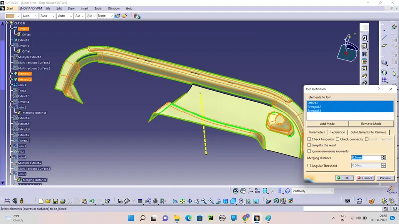
And join with main class B.
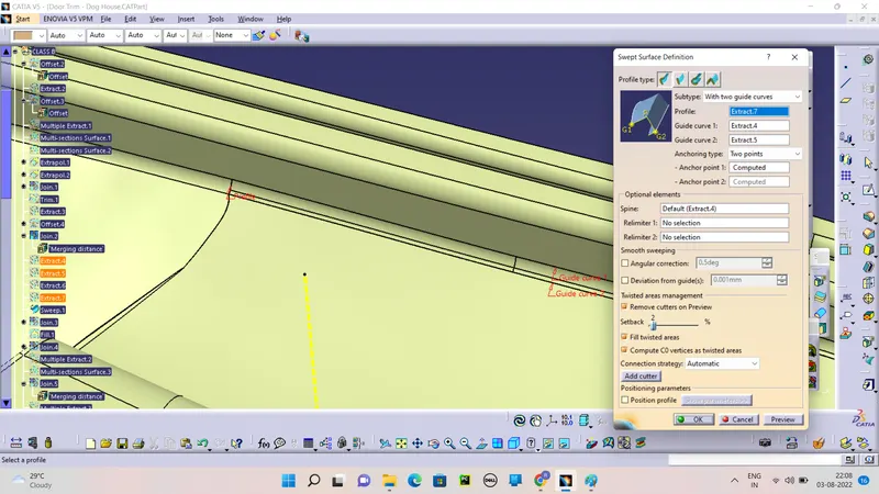
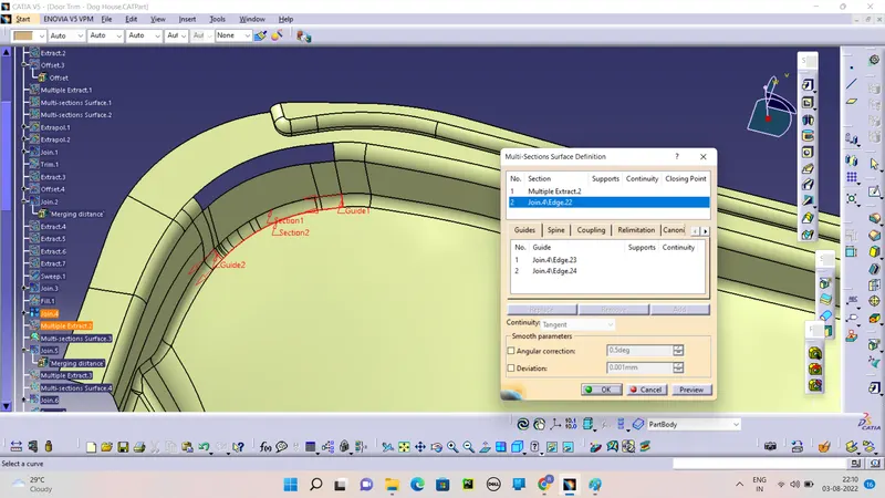
Fill the small patch by the Multi Section Surface and Sweep.
Like wise create to all patch and join with existing surface and extrapolate for require length.
CREATE CLASS C:
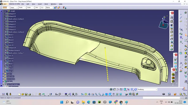
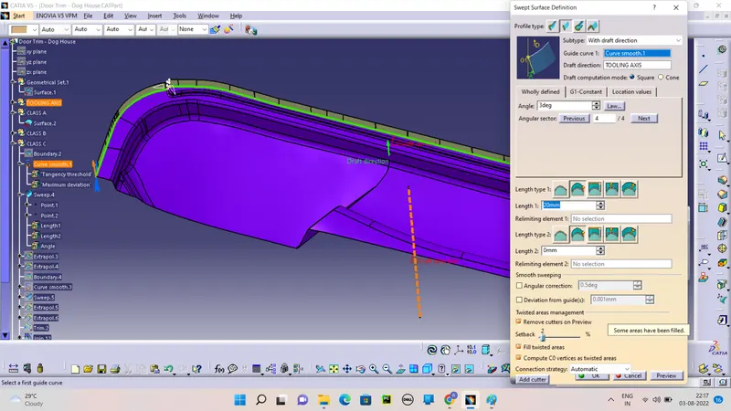
Create the class C from the Class A by the Sweep command. Extract the boundry and smooth the curve by the Smoothy curve and Sweep the Curve by the Refer Draft Direction.
Likewise create the all side of sweep of Class C.
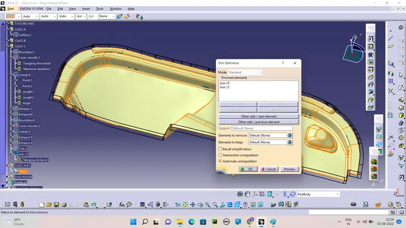
Class C join with Class A.
Class A C Trim with Class B.
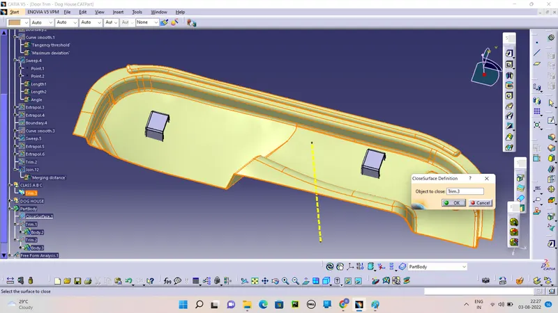
Create the Solid part by the close view option in Part workbench.
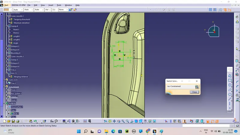
Create the Dog House on the Solid part So first we want point and Axis system on the part for Dog House.
Sketch on the part by the Positioned sketch.
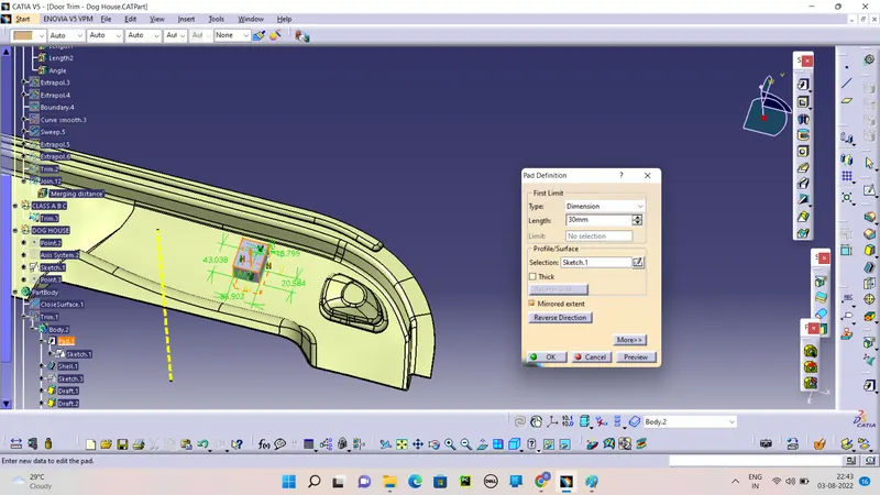
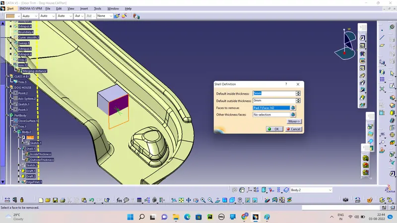
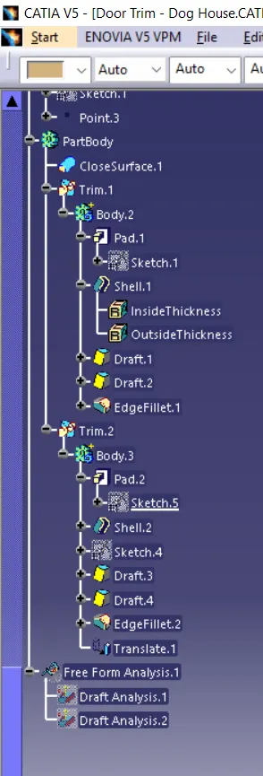
Pad it and Shell the Solid part.
And Shell it.
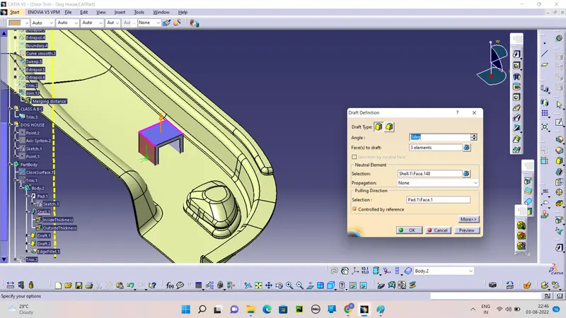
And Draft it .
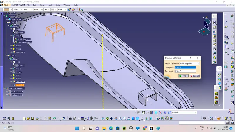
Translate it by the poit to point Translate.
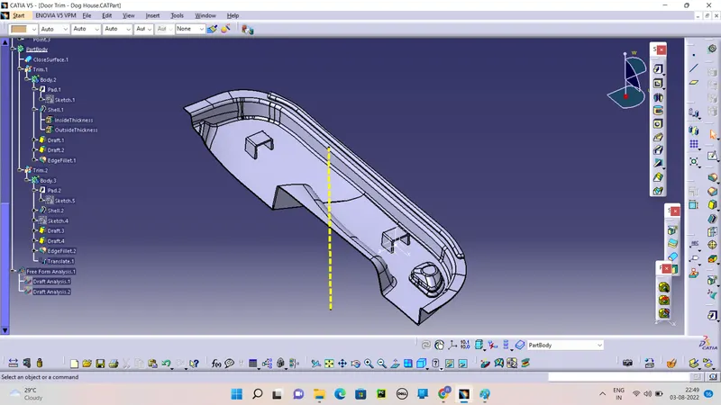
Get Final Part.
CREATE THE TOOLING AXIS FOR THE DOG HOUSE:
Create the tooling Axis from the Existing point.
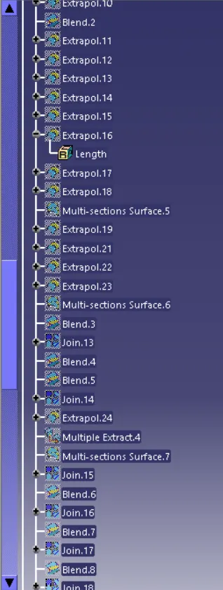
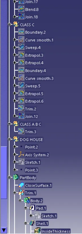
TREE STRUCTURE:
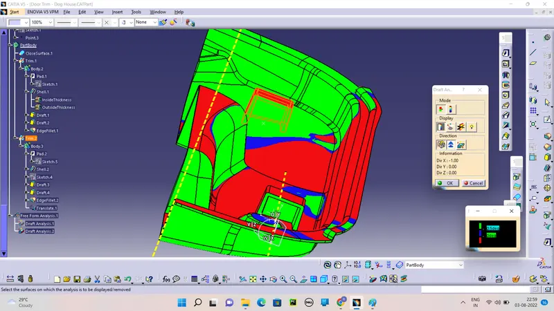
DRAFT ANALYSIS FOR DOG HOUSE:
Check the Draft analysis for the Dog house.
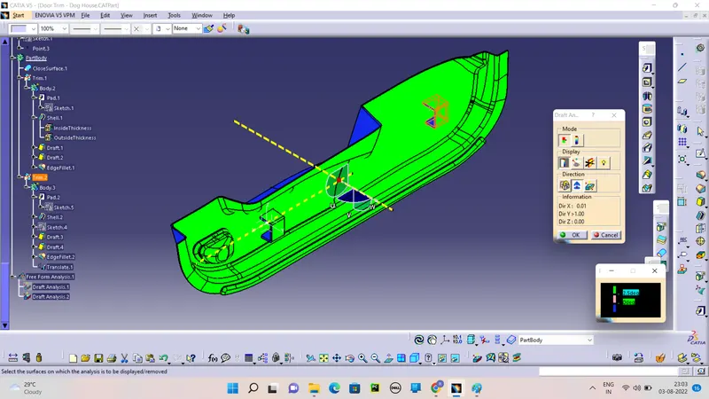
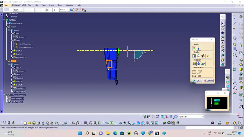
3D PART ORIETATION WITH DRAFT ANALYSIS:
ISOMATRIC VIEW:
FRONT VIEW:
SIDE VIEW:
TOP VIEW: