Week 9 - Attachment Feature Creation - Challenge 2
INTRODUCTION-
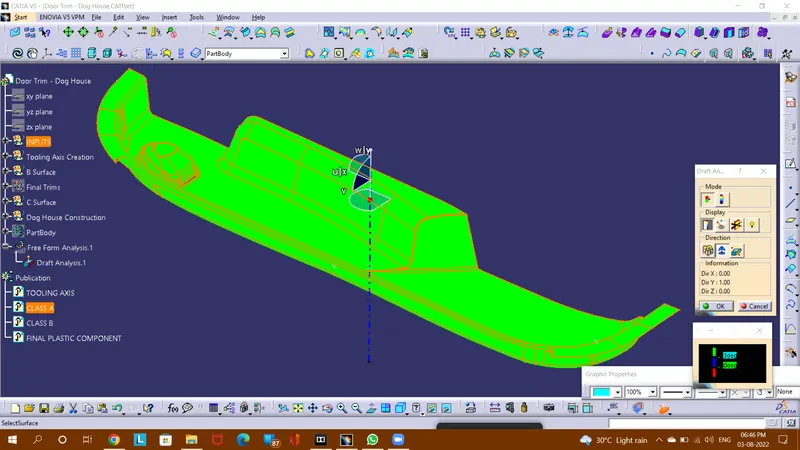
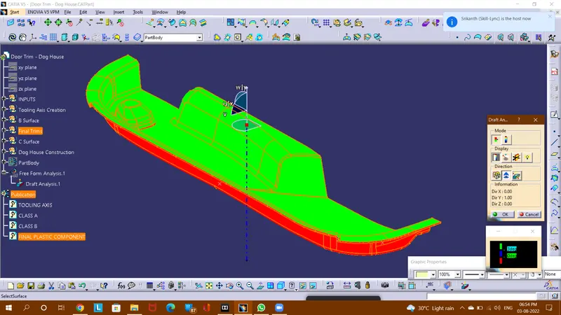
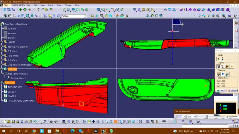
Draft Analysis is performed virtually in order to check the draft angle of the designed part for smooth ejection processes from the mold, when manufactured in the real environment. It performs the analysis on the basis of colors' ranges that dignifies and differentiate the surfaces through colors on the basis of their angles.
Tooling Axis is done in order to find the easiest possible direction of the part ejection from the mold, when manufactured in the real environment. For eg.- A part with holes can be easily ejected along the direction normal to it, hence tooling axis is taken normal to holes.
Class A surface-
Final Plastic Component-
Solid Part-
PROCEDURE-
Tooling Axis creation-
- Since it is cleared through the given class A surface that its main tooling axis will lie perpendicular to the bottom surface due to smooth ejection when manufactured and it isn't needed to apply bisecting method through the side walls. So (here) a point is needed to be taken at mid of surface then through point a line will be extended which will be the Main Tooling axis.