Week 8 - Challenge 1 - Base Bracket Design
INTRODUCTION-
Draft Analysis is performed virtually in order to check the draft angle of the designed part for smooth ejection processes from the mold, when manufactured in the real environment. It performs the analysis on the basis of colors' ranges that dignifies and differentiate the surfaces through colors on the basis of their angles.
Tooling Axis is done in order to find the easiest possible direction of the part ejection from the mold, when manufactured in the real environment. For eg.- A part with holes can be easily ejected along the direction normal to it, hence tooling axis is taken normal to holes.
Class A surface-
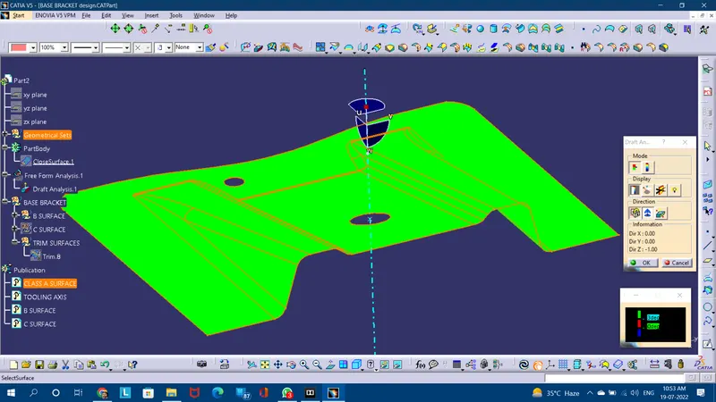
Final plastic component-
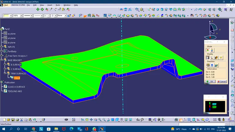
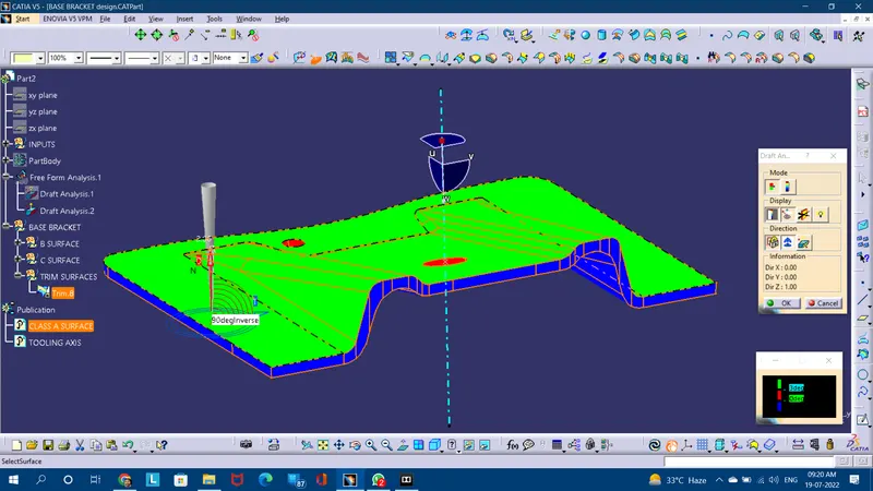
Solid part-
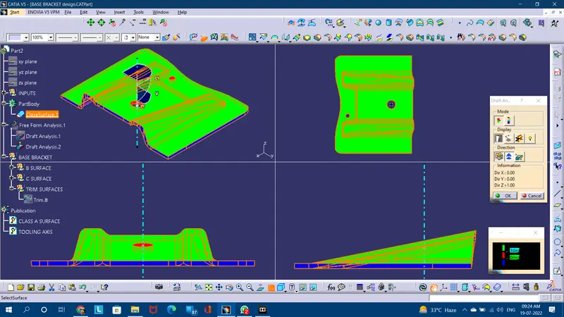
PROCEDURE-
Tooling Axis creation-
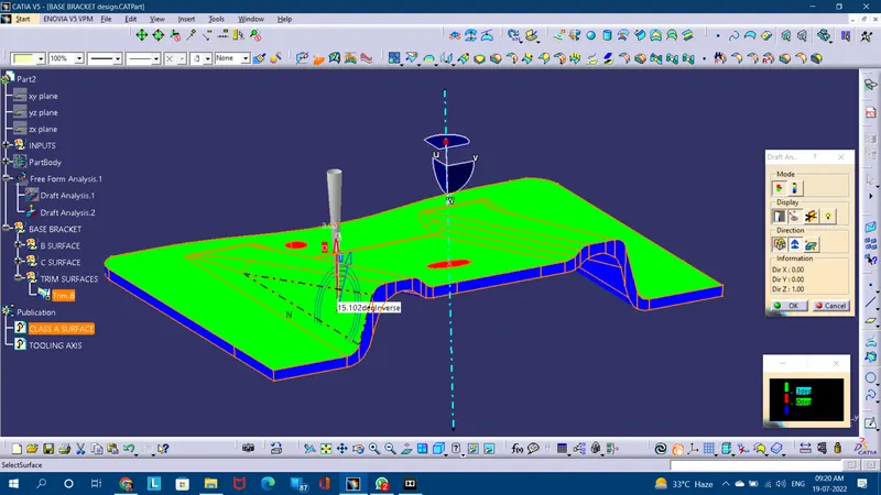
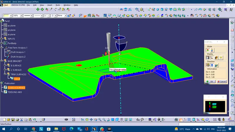
- Before tooling axis creation the part should be analysed from all 3 directions for smoothest ejection, in the below given Class A surface tooling axis perpendicular to the given view isn't possible as the mold cavity will get stuck in between the surfaces of 2nd image.
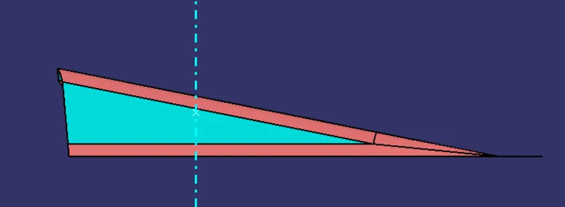
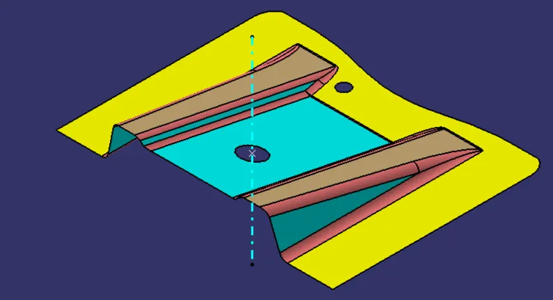
- Switching to this view, it could have followed a smooth part ejection from mold but due to those holes it is now impossible to eject.
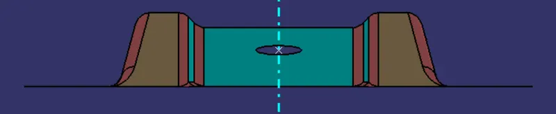
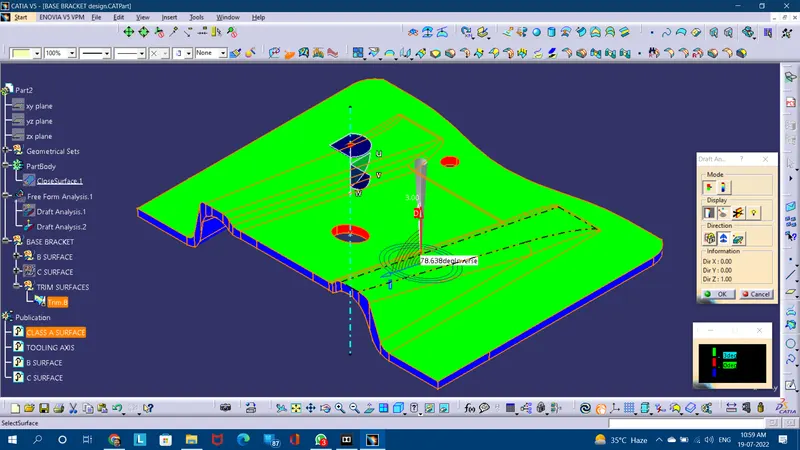
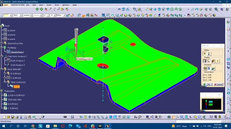
- Switching to this view, it is completely possible for the core and cavity to eject smoothly this part, So the tooling axis will be taken normal to the bigger hole surface.
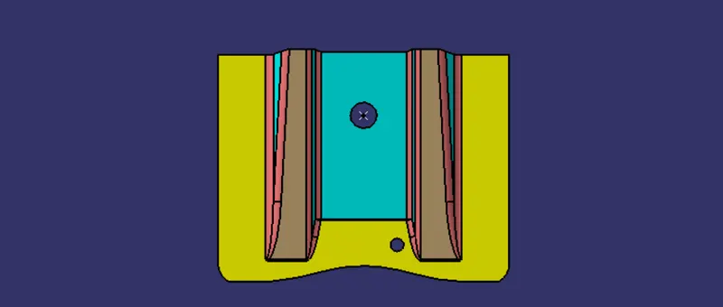
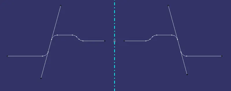
- After selecting the direction take a plane perpendicular to the part and parallel to the cross section of the part in order to project the cross section(given below) lies on that plane through intersection method.
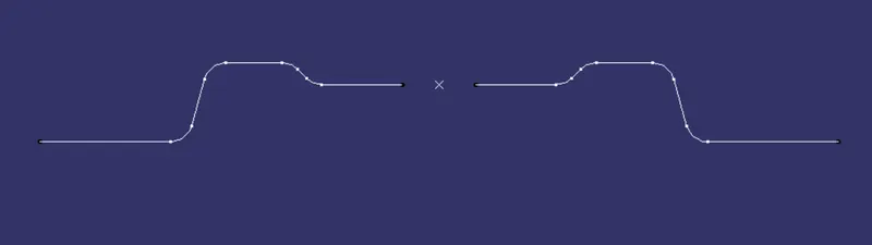
- Then extend the lines from the drafted side of this cross-section, and create resulting tooling axis through bisecting method