Attachment Feature (Screw boss and Dog house) Creation For Coin Holder
DRAFT ANALYSIS ON COIN HOLDER AND ITS ATTACHMENT FEATURES
Objective:
The main aim of this report is to explain how the tooling axis was created for the given class A surface of a centre console coin holder and the steps involved in draft analysis with respect to the created tooling axis. And then the creation of class B & C surface from the class A, to create solid part out of those surfaces and attachment features.
Description:
Class A surface:
The class A surface of a centre console coin holder is given to do the draft analysis and to create class B & C surface for solid part creation.
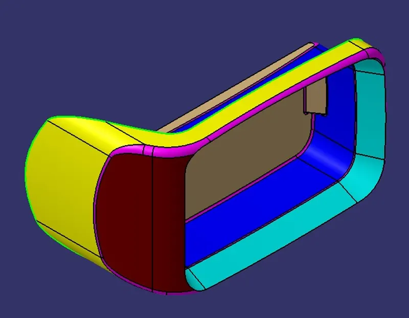
Isometric view of the given class A surface of coin holder.
Test-1:
In this test the surface continuity of the given class A surface is examined to avoid gaps. If any gaps or discontinuity is present in the class A surface, we cannot thicken or use closed surface command to create a solid part out of it.
Joining:
By applying joining command to the class A surface, we can test the continuity of the class A surface of the given coin holder by examining its edges.
Boundary:
By applying boundary command to the class A surface of the coin holder, we can create a boundary line of the open edges. With help of this boundary line the continuity is tested visually.
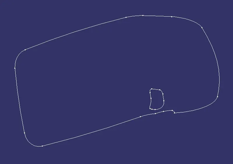
Boundary of class A surface shown in the above picture.
If any gaps or discontinuity in the class A surface is found we have to correct it for further process.
We can use either joining or boundary command for this test.
Test-2:
In this test, the tooling axis is created along the x, y and z directions, to choose the best tooling axis out of it, for reducing the tooling cost.
For this given class A of coin holder, it contains a slot in the side wall of the pocket area. So, this slot cannot be visible in all the three directions (x, y &z).
For this type of class A we have to create the tooling axis normal to the flat surface in it, to achieve the best suited tooling axis for manufacturing the component in a cost effective way.
Tooling axis:
Tooling axis is used to define the direction of core and cavity movement of a moulding machine according to the component to be moulded.
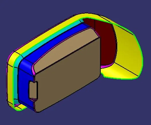
Isometric view.
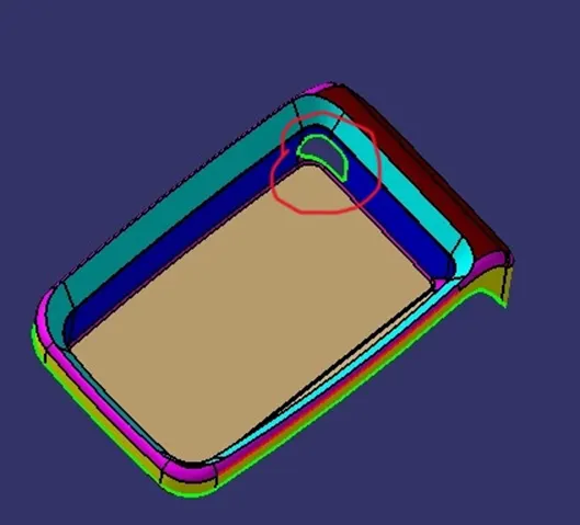
Tilted view of class A surface.
As we seen early, the marked hole in the tilted view cannot be achieved in X, Y, & Z directions.
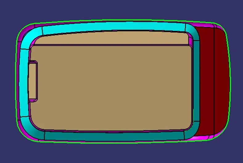
The given class A surface of coin holder along X axis.
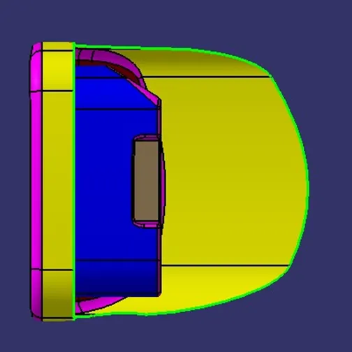
The given class A surface of coin holder along Y axis.
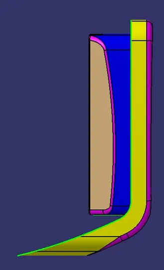
The given class A surface of coin holder along Z axis.
With reference to the pictures, the only way of creating the tooling axis is, to create a point in the flat surface of pocket area.
After creating the point on the surface, an axis system is created about that point, then a line created normal to that surface is considered as the final tooling axis for the given class A.
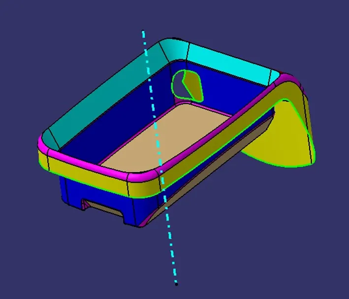
Final tooling axis is shown.
The tooling axis for the given class A has been created along the y direction of the newly created axis system.
- This tooling axis decides the movement direction of core and cavity to manufacture the coin holder.
Draft analysis:
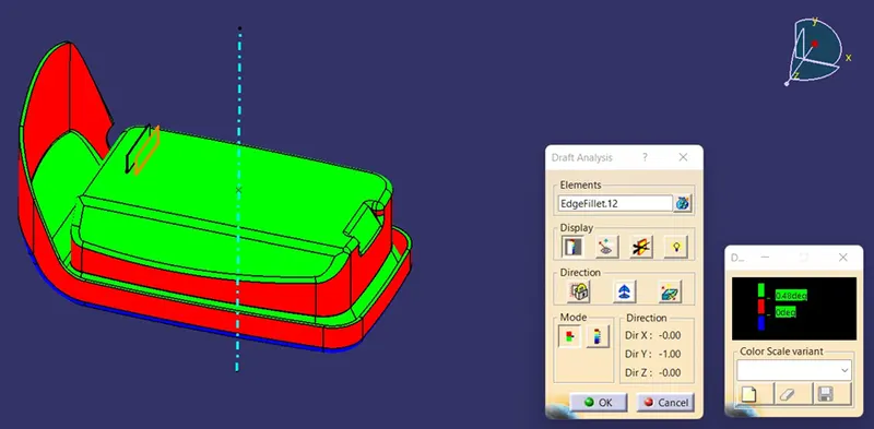
The draft analysis command enables you to detect if the part you drafted will be easily removed. This type of analysis is performed based on color ranges identifying zones on the analysed element where the deviation from the draft direction at any point, corresponds to specified values.
Draft analysis is carried out to check the drafts in the class A surface of coin holder is feasible. The nominal draft for plastic components is 3º and 0.5º is the minimum draft value.
- After the creation of tooling axis, the feature draft analysis command is applied to do the analysis.
- By using the direction tool, the compass to define the new current draft direction is placed along the tooling axis. Then the draft direction is locked.
- In the display tool, the color scale is opened to give the limits for the draft analysis and then the surface is selected to test the draft for the given limits. If the color of the surface is changed to green, then the draft of that component is able to be manufactured.
- If the color of the surface is changed to red, then the class A surface is failed in draft analysis test and it is difficult to manufacture the component in cost effective manner.
- In this case, the class A surface of coin holder is passed in the draft analysis and the part body of it can be created for further process.
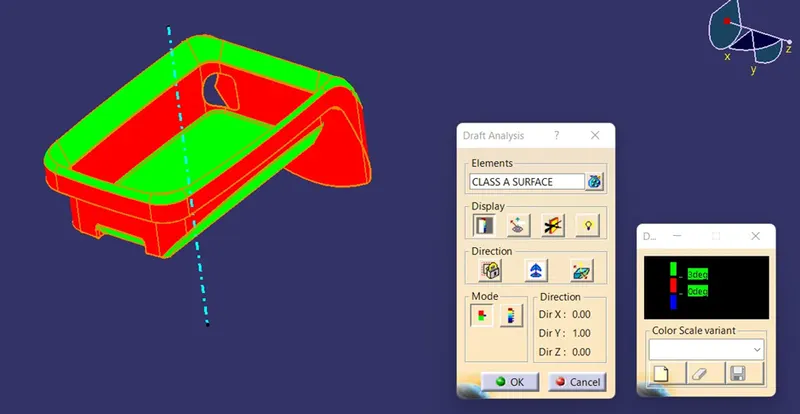
Draft analysis of the class A surface with nominal draft is shown in the picture.
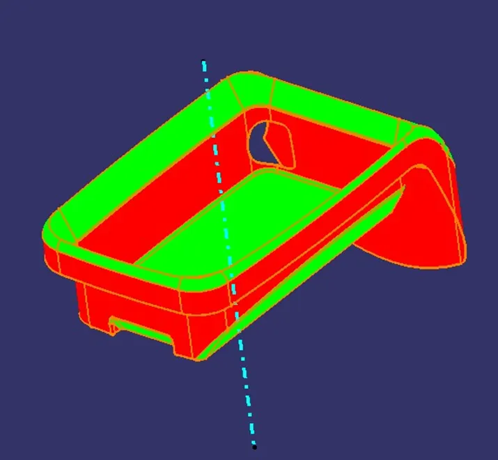
Draft analysed class A of coin holder is shown.
Some of the surfaces on given class A is completely parallel to the tooling axis. So, the red color is indicated for that surfaces.
If we have the approval to further processing of the given Class A, then we ignore those surfaces.
The same procedure is followed to conduct draft analysis on the solid part also,
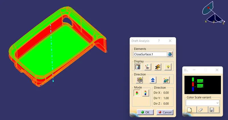
Draft analysis of the coin holder part with nominal draft is shown.
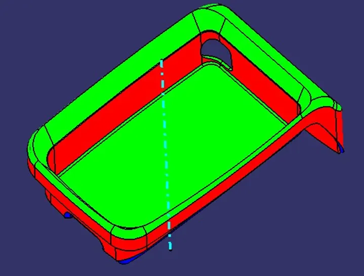
Draft analysed coin holder part is shown.
B Surface:
B surface are said to be the engineering surface which has all the ribs and fixing elements in it. This B surface is created with reference to the given class A surface.
- After completing the draft analysis, if the class A surface is passed then the class B surface creation starts.
- Extract the necessary surface from the class A and untrim those surfaces to extrapolate it.
- After the extrapolation, trim command is applied to remove the unwanted surfaces.
- Then this surface is offset to the required thickness value and then the fillets were applied.
- This offset surface is said to be class B surface.
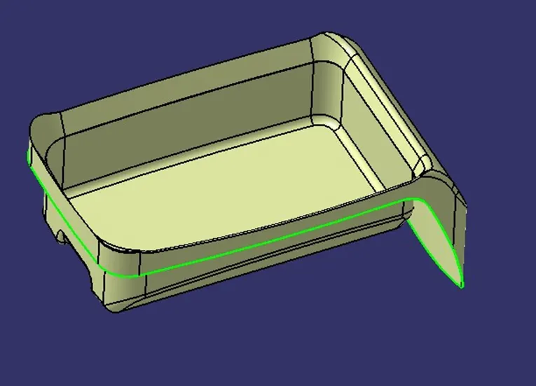
B surface shown in the above picture.
C Surface:
C surface are said to be the connecting surface of class A surface with the B surface.
- Boundary command is applied to the open edges of the class A surface to create a boundary line or multiple extract command is applied to extract the open edges.
- This boundary line or extracted line is used to create the sweep along the draft direction or perpendicular to reference surface with enough value to overlap the B surface.
- It is said to be class C surface.
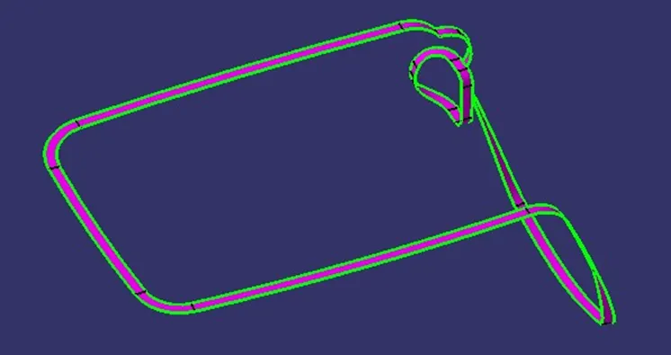
C surface shown in the above picture.
Closed surface:
Closed surface is the final surface used to create the solid part by applying the closed surface command in the part workbench.
- After the creation of class A, B & C surfaces, they are joined and trimmed to form the closed surface.
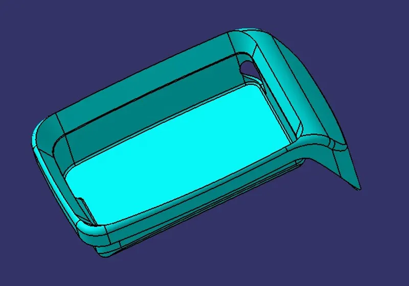
Closed surface is shown.
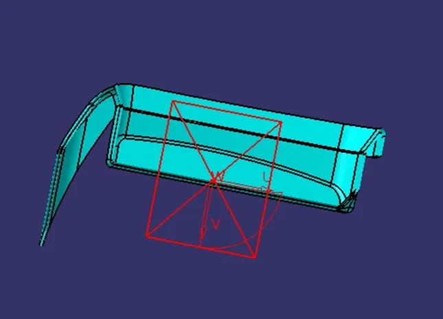
Sectioned view of closed surface.
Solid part:
Solid part is created by applying the closed surface command in the part workbench to the closed surface, which is created with the help of class A, B & C surfaces in the surface workbench.
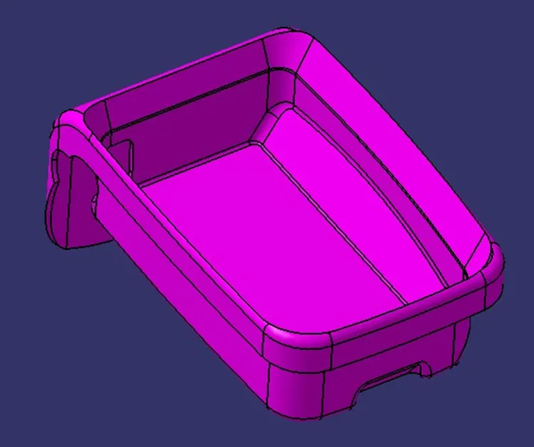
Isometric view of coin holder part.
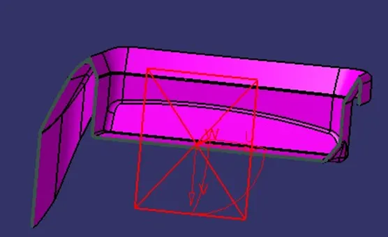
Sectioned view of coin holder part.
Attachment features:
Attachment features are the features present in B surface of the component, which are used to increase the stability and durability of the components to serve its purpose. It is also important to assemble or fix the components together in an efficient way.
Some important attachment features are:
- Ribs
- Screw bosses
- Dog house designs.
Ribs:
Ribs are thin protrusions that extend perpendicular from a wall or plane to provide added stiffness and strength to the component or part. Ribs are used to reduce the manufacturing cost of components without compromising its stability and durability.
For the given centre console coin holder, one of the attachment features, ribs were created by following the standard design rules. The steps are as follows:
- After solid part creation of coin holder, its attachment features creation on its B surface is carried out to create some ribs.
- The flat surface on the B surface is extracted, then some positioned sketches were created with reference to the extracted surface.
- Those sketches were padded along the tooling axis with some thickness and height value. “The standard thickness of ribs are 0.4 times or 40% of the components wall thickness and the height of ribs are 5 times the wall thickness”.
- After padding, all sides of the ribs were drafted along the tooling axis. “The standard draft for ribs is greater than are equal to (5º)”.
- Then this rib parts are assembled with coin holder by applying the assemble command on the Boolean operation.
- After that, fillets were applied to rib edges. “The standard fillet radius for ribs is maximum of 0.25mm”.
- The minimum gap between the ribs is 2 times the wall thickness of the component.
- After the ribs creation, its root thickness is measured to ensure its standard value is achieved to avoid the plastic defects in the component.
- The root thickness is said to thickness at the junction were the ribs and the component are connected, it does not exceed 30% of component wall thickness according the design standards.
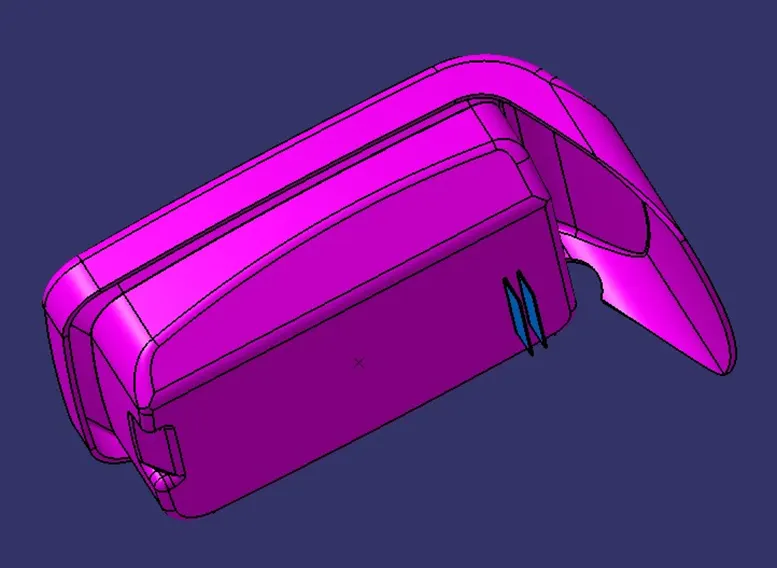
Coin holder with attachment ribs is shown.
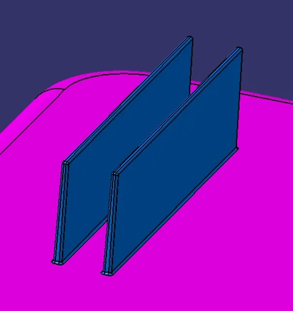
Ribs.
Draft analysis on ribs:
The draft analysis on ribs is conducted, to ensure its feasibility to manufacture. The same procedure is followed to do the draft analysis like before,
Draft analysis of attachment ribs with standard draft value is shown.
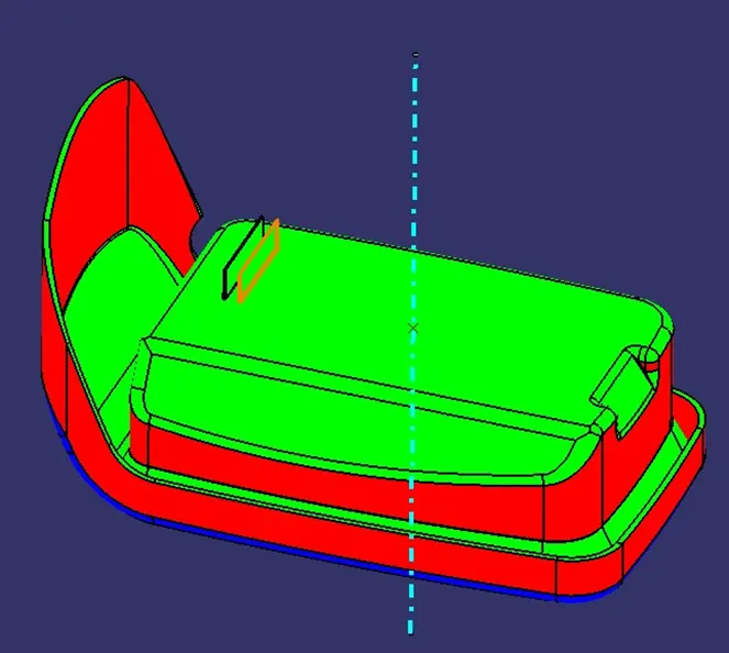
Draft analysed ribs attached with component is shown.
The created ribs are passed in the draft analysis.
Screw boss:
Screw bosses are the elements present in the B surface, which are used to assemble or fix components together in its position by arresting its freedom. In other words, a boss is a cylindrical protrusion placed on a part’s wall. A boss can have various functions, such as the following:
- Positioning aid – To help align parts during assembly; for example, a pin on one part will fit a hole in the other part.
- Fixation point – In the example mentioned above, the pin and hole can have a press fit. Friction between the two keeps the parts fixed. A boss can also be a tubular protrusion that can accommodate self-tapping screws to fix other parts.
- Bearing surface – A cylindrical protrusion can act as a bearing for another part; for example, a lever or a gear to rotate about.
Screw boss standards:
The following standards are obtained from trail & error method by the OEM’s and automotive industries,
- The minimum draft of 0.5º is must to the outer and inner surface of the screw bosses to eject it from the mould.
- The common fillet radii for the screw boss is 0.25mm to reduce the turbulence and increased flow while injecting the molten plastic material into the mould.
- Wall thickness at each side should have 0.4 times the nominal wall thickness.
- Height of the screw boss must 5 times the wall thickness or in 3:1 ratio.
For the coin holder component, the attachment feature screw bosses were created following the above-mentioned standards.
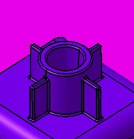
Screw boss for coin holder is shown.
Dog house:
Dog house is one of the attachment features used to support the screw bosses and other features in an elevated position to reduce the manufacturing cost of the component. It is present in the B or C surface according to its requirement.
Dog house standards:
- The thickness at the C region (C region is where the dog house contacts components wall) should be 40% of the main wall thickness to avoid the sink marks.
- The height of the B region (B region is where the thickness increases in the dog house) should be in between 3-6mm.
For the coin holder component, the attachment feature dog houses were created following the above-mentioned standards.
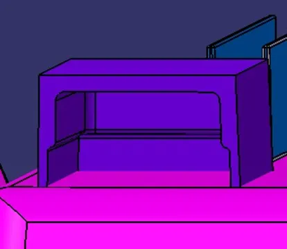
Dog house for coin holder is shown.
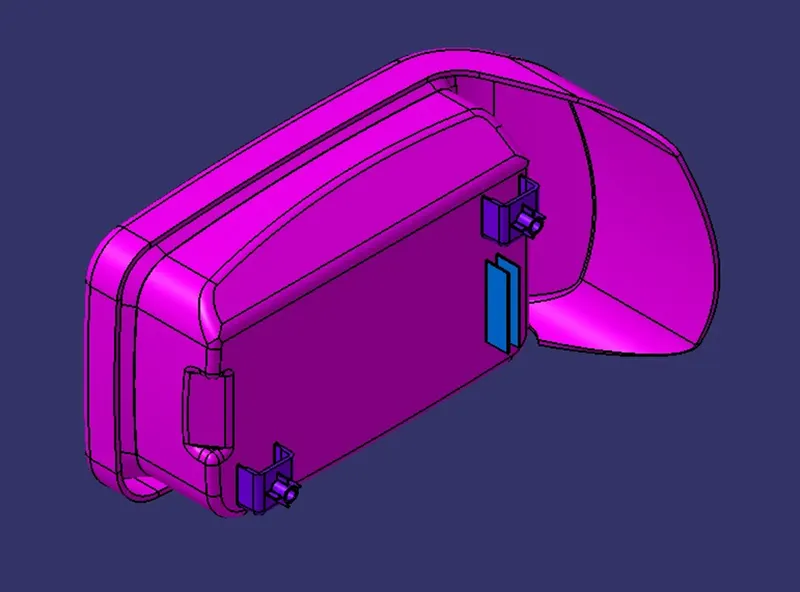
Coin holder with attachment features is shown.
Draft analysis on dog house and screw boss:
The draft analysis for dog house requires side core axis. Because it cannot be achieved by the core & cavity itself.
Side core: side core is an extra core which is used to manufacture the components which cannot be manufactured by core and cavity itself. It has separate tooling axis for its movement.
Side core axis: side core axis is used to define the movement direction of side core in the moulding operation.
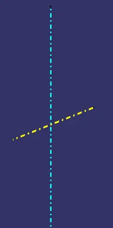
Side core axis.
The side core axis is created along the z direction with reference to the point which is created about the surface for the attachment features of coin holder component.
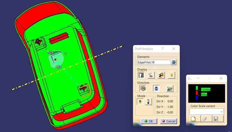
Draft analysis on dog house along main tooling axis is shown.
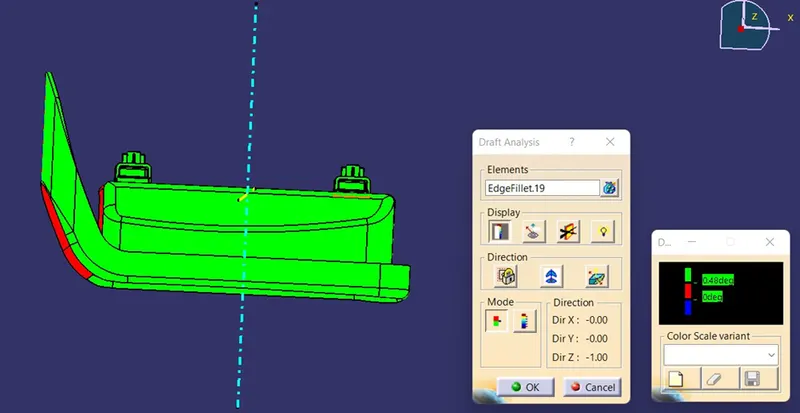
Draft analysis on dog house along main side core axis is shown.
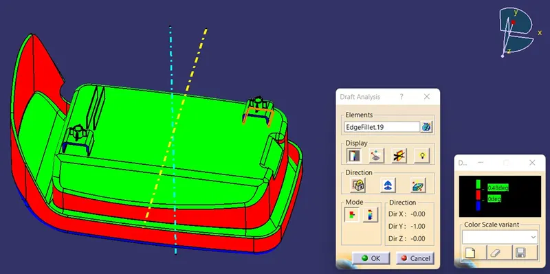
Draft analysis on screw bosses is shown.
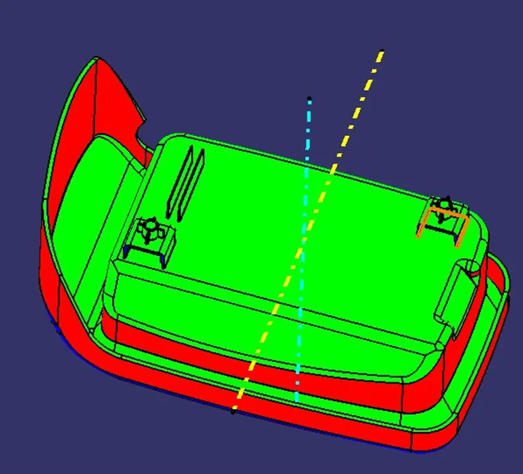
Draft analysed attachment features along with the component is shown.
Conclusion:
The creation of tooling axis and the steps involved in draft analysis of centre console coin holder is explained in detail with respect to the reference images regarding to the given class A surface of the same. And, the steps involved in class B & C surface, solid part and attachment features creations are also explained in detail with some reference images. For the given coin holder component, I have the approval to create it even though it was failed in draft analysis.