Designing of Sunseeker Predator Yacht & its Assembly with Photo Realistic Rendering using – “SOLIDWORKS and SOLIDWORKS Visualize”.
Designing of Sunseeker Predator Yacht & its Assembly with Photo Realistic Rendering using – “SOLIDWORKS and SOLIDWORKS Visualize”.
Objective:
To design a Sunseeker Predator Yacht from blueprint setup to fully defined model for final rendering with my interests towards design and to develop my skills in design to next level using – “SOLIDWORKS and SOLIDWORKS Visualize” software.
Introduction:
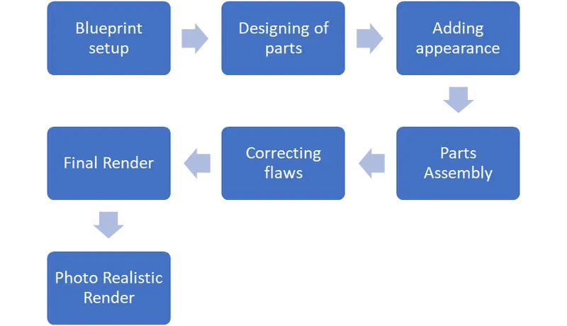
This report is fully about how an Sunseeker predator yacht (A yacht is a sailing or power vessel used for pleasure, cruising, or racing) designed from,
- Setting up the 2D images of yacht model as base of reference for “Blueprint setup”.
- Blueprint setup to designing of parts with appropriate dimensions.
- Adding appearance to the parts.
- Assembling the parts designed by using - “SOLIDWORKS”.
- Correcting the flaws in the assembled model.
- Final render of Sunseeker predator yacht.
- Photo Realistic Rendering using - “SOLIDWORKS Visualize”.
Process plan for Design:
Blueprint Setup: The different views of 2D images of already available yacht model were placed in the appropriate planes to form a 3D base as a reference to design parts.
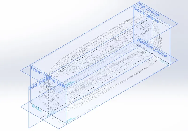
Isometric view of Blueprint setup shown in the above picture.
Parts to Design:
- Propeller
- Radar
- Hull
- Garage Door
- Front Seat
- Middle Seat
- Rear Seat
- Superstructure
- Radar Mast.
Feature and Surface Tools used:
|
: |
This feature will allow you to take a 2D sketch and add thickness to it in the third dimension. |
|
: |
This feature will allow you to remove material from the part by projecting a sketch section normal to the sketching plane. |
|
: |
It is used to create solid 3D model around an axis |
|
: |
This feature tool is helps to create 3D product design parts by sweeping. Some of the application examples are create spring model, complex hollow pipes, air conditioning ducts, curved rods, tubes, twisted parts, etc… |
|
: |
Mainly helps to add materials between two or more profiles with ease. |
|
: |
Fillet creates a rounded internal or external face on the part. It is mainly used on the edges and corners of faces or parts. |
|
: |
It creates a bevelled feature on selected edges, faces or a vertex. It is used to create sloped or angled edges. |
|
: |
Are used to create multiple instances of one or more features that you can space uniformly along one or two linear paths. |
|
: |
This feature helps to create multiple instances of one or more features that you can space uniformly around an axis. |
|
: |
This command creates a copy of a feature, (or multiple features), mirrored about a face or a plane. |
|
: |
It is used to create a hollow space within a solid part according to its thickness value given, mainly used in tank designs. |
|
: |
It helps to create projection of two sketch in different intersecting planes and this curve is used as a path for sweep. |
|
: |
It allows you to combine curves, sketch geometry and model edges into a single curve and this created curve is used as a guide curve for creating a loft or a sweep. |
|
: |
This tool projects an entity (sketch, solid, surface, face, plane, or surface spline) to surface, or curved or planar faces. |
|
: |
To create a helix/spiral like path or guide curve for a swept feature or lofted feature. |
|
: |
It helps to create a plane within the sketches and it is added to facilitate an extruded cut on a non-planar face. |
|
: |
It creates a hollow half sphere that is tangent to the adjacent cylindrical or conical face. |
|
: |
It allows you to add two bodies together, and keep the area that is common to them. |
|
: |
We can extrude the boundary edges of a face of a solid body or edges of a surface body in a customized direction by using this feature. |
|
: |
Used to generate surfaces from a section curve positioned along a path. |
|
: |
It helps to create surfaces with a smooth tangency between the selected curves by multiple 3D curves or existing edges. |
|
: |
This tool is used to combine two or more faces and surfaces into one. |
|
: |
Used to trim the extra projection of surfaces which are intersecting or overlapping. |
|
: |
The filled surface feature constructs a surface patch with any number of sides, within a boundary defined by existing model edges, sketches, or curves, including composite curves. |
|
: |
This feature helps to extend a surface by selecting an edge, multiple edges, or a face. |
|
: |
It creates surfaces that extend out in a specified direction from selected edges. |
|
: |
It creates a new surface body from an existing set of faces. |
- Propeller:
A propeller is a device with a rotating hub and radiating blades that are set at a pitch to form a helical spiral, that, when rotated exerts, linear thrust upon a working fluid, such as water or air. Propeller are used to create thrust to propel the boat through water.
- The design of propeller is done by choosing appropriate planes in the “SOLIDWORKS” work window to create some 2D sketches.
- Then using the feature tools 2D sketches are converted to 3D part.
- After creating part, fillet applied to its edges.
- Feature tools used: Revolved boss/base, Reference plane, Lofted boss/base, Fillet, Extruded cut, Circular Pattern.
- Appearance: Customised colour applied to the part.
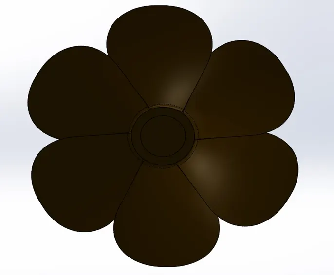
Front view.
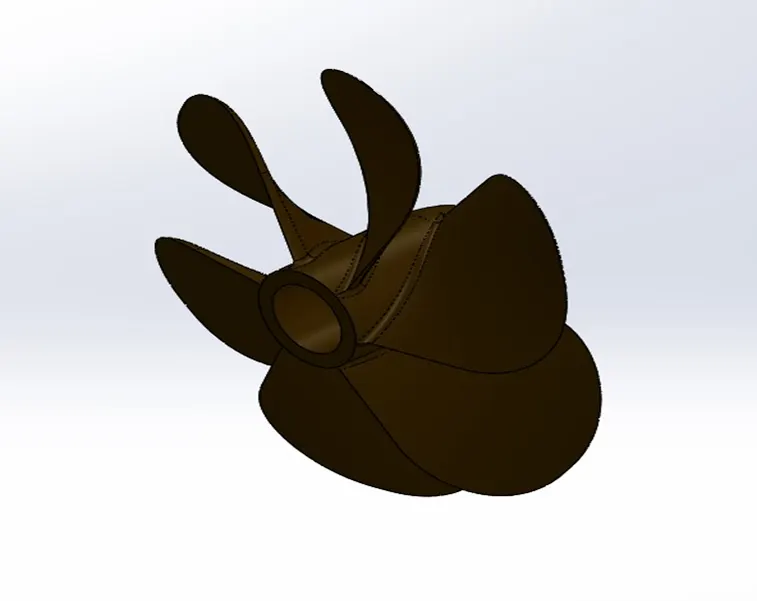
Isometric view of Propeller is shown in the above picture.
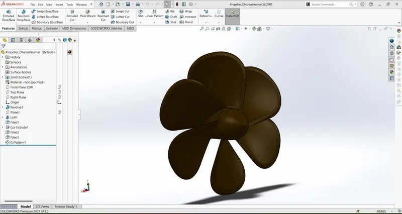
“SOLIDWORKS” work window sample shown in the above picture.
- Radar:
Radar (Radio Detection And Ranging), is a detection system that uses radio waves to determine the distance(ranging), angle, and radial velocity of objects relative to the site. It can be used to detect aircraft, ships, spacecrafts, guided missiles, motor vehicles, weather formations and terrain.
- Creating new sketches on the appropriate planes.
- Giving required dimensions to fully define the sketch.
- With the help of feature tools 3D part created based on the drawn 2D sketch.
- After the part creation a text is created on the front face, then fillets applied to the edges.
- Feature tools used: Extruded boss/base, Fillet, Sketch driven pattern, Extruded cut, Mirror, Text & Split line.
- Appearance: White colour applied to the part & custom dark grey colour applied to the text.

Back view.
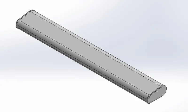
Isometric view of Radar shown in the above picture.
- Hull:
A Hull is a watertight body of a ship, boat or flying boat. The hull may open at the top, or it may be fully or partially covered with a deck. The deck may be consisting of deckhouse or other superstructures, such as a funnel, derrick, or mast at the top.
- Creating sketches on the appropriate planes.
- Giving required dimensions to fully define the sketch.
- With the help of feature tools 3D part created based on the sketch drawn previously and then a solid body made using this part.
- Then shell applied to the solid body to create a vacuum chamber inside the hull part.
- The extra projections and overlapping geometry of the part were trimmed.
- Mirror pattern applied to the parts to form a complete hull about the planes & faces.
- Fillets and Chamfers were applied to the required edges.
- Decals applied to the deck surface and to the required areas.
- Feature tools used: Projected curve, Loft surface, Surface trim, Surface extrude, Surface knit, Surface fill, Shell, Extruded boss/base, Extruded cut, Fillet, Chamfer, Reference plane, Linear pattern, Swept boss/base, Revolved boss/base, Dome, Helix/spiral, Projected curve, Face delete, Mirror, Combine & Surface offset.
- Appearance: White, Dark blue and some custom colours applied to this part.
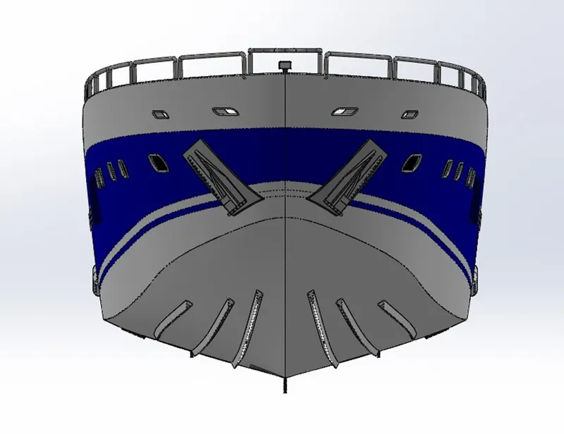
Front view.
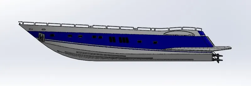
Side view.
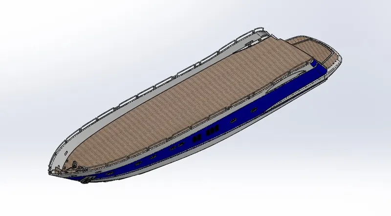
Isometric view of Hull shown in the above picture.
- Garage door:
A garage door is a large door on a garage that opens either manually or by an electric motor. Garage doors are frequently large enough to accommodate automobiles and other vehicles.
- Creating sketches on the cut-out body of the hull to cut down the extras.
- Giving required dimensions to fully define the sketch.
- With the help of feature tools and using the sketches the extra materials were cut down rather than the required door part.
- Fillets were applied to the edges and then mirror applied to the bodies about appropriate plane or faces.
- Then texts were created on one of the face on the garage door.
- Feature tools used: Extruded cut, Shell, Fillet, Mirror, Reference plane & Text.
- Appearance: Dark blue colour applied to the part and dark grey colour applied to the text.
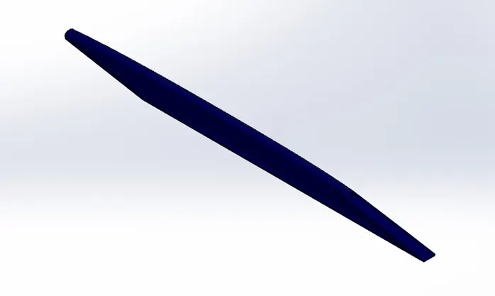
Isometric view.
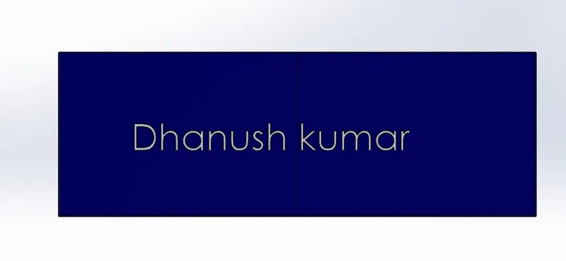
Back view of Garage door shown in the above picture.
- Front Seat:
Front seat is placed at the front side and at the top of deck surface of the hull to fulfil yacht model and it adds great look to the yacht.
- Creating sketches on the appropriate planes.
- Giving required dimensions to fully define the sketch.
- 3D Surfaces created using the defined sketches.
- Then the extra projection & overlapping geometry were trimmed.
- These surfaces were knitted to form a single surface.
- Fillets and Chamfers were applied to the edges.
- Mirror applied about the plane & faces of the part to complete the model.
- Feature tools used: Reference plane, Surface sweep, Surface extrude, Surface trim, Surface fill, Surface loft, Surface knit, Chamfer, Revolved boss/base, Extruded cut, Fillet, Mirror & Dome.
- Appearance: White & light grey colours applied to this part.
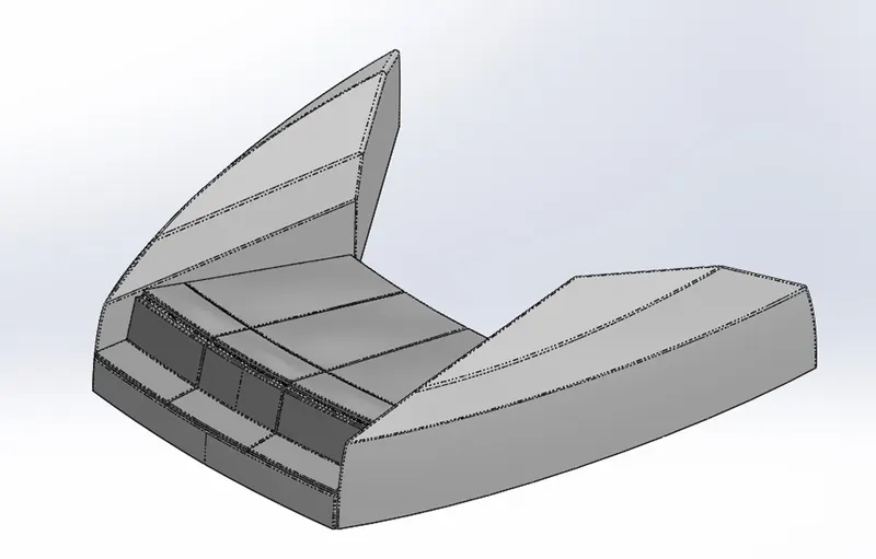
Isometric view of Front seat shown in the above picture.
- Middle Seat:
Middle seat is placed behind the superstructure at the deck surface of the hull. This seat consisting a table at its centre and provides good relaxing space to enjoy the views, it also fulfils the yacht model with great looks.
- Creating sketches on the appropriate planes.
- Giving required dimensions to fully define the sketch.
- 3D parts created using the defined sketches.
- Fillets and chamfer applied to the edges.
- Mirror applied about the plane and faces of the parts.
- Feature tools used: Extruded boss/base, Reference plane, Chamfer, Fillet, Mirror & Extruded cut.
- Appearance: White, light grey, custom grey and brown colours applied to these parts.
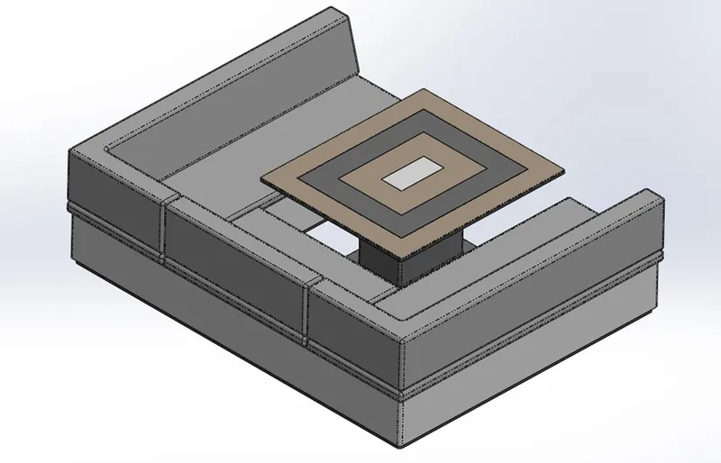
Isometric view of Middle seat shown in the above picture.
- Rear seat:
Rear seat is placed at the backside of hull and on the deck surface near the stairs. This seat consisting of storage Compartments, flag pole, small gates and provides space for fishing, it also fulfils the yacht model to a whole one with its design.
- Creating sketches on the appropriate planes.
- Giving required dimensions to fully define the sketch.
- 3D Surfaces created using the defined sketches.
- Then the gaps in these surfaces were filled and ruled.
- The extra projections and overlapping of the surfaces were trimmed.
- After trimming the surfaces are knitted to form a single surface model.
- After creating part linear pattern applied at the desired faces.
- Fillet & chamfer applied for the corresponding edges.
- Feature tools used: Reference plane, Surface sweep, Surface offset, Surface trim, Ruled surface, Surface knit, Surface extend, Surface extrude, Surface loft, Extruded boss/base, Extruded cut, Chamfer, Fillet, Swept boss/base, Mirror & Revolved boss/base.
- Appearance: White, grey and light grey colour applied to the seat and pole; Custom colour applied to the flag.
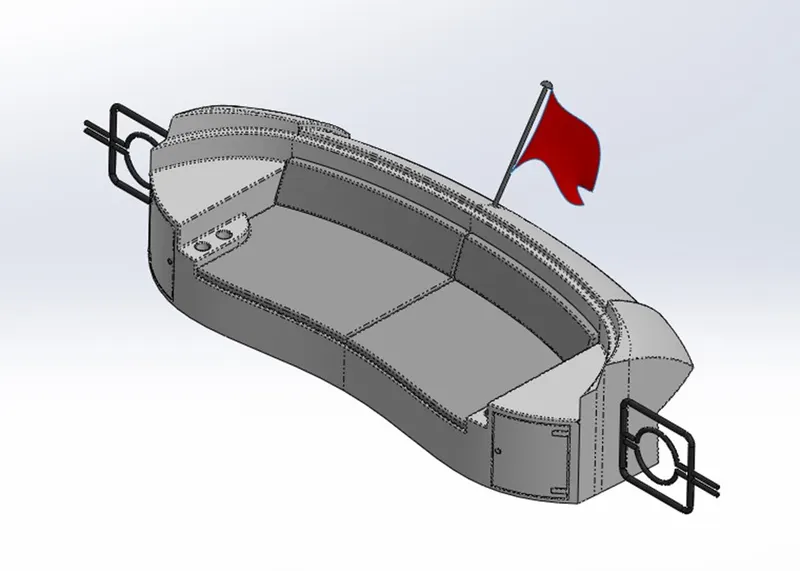
Isometric view of Rear seat shown in the above picture.
- Superstructure:
A Superstructure is an upward extension of an existing structure above a baseline. On watercrafts, the superstructure consists of the parts of the ships, or boats, including sail boats, fishing boats, passenger ships, and submarines, that project above her main deck.
- Creating sketches on the appropriate planes.
- Giving required dimensions to fully define the sketch.
- 3D Surfaces created using the defined sketches.
- Then the gaps in these surfaces were filled and ruled.
- The extra projections and overlapping of the surfaces were trimmed.
- After trimming the surfaces are knitted to form a single surface model.
- Wipers were created over the windshield of the superstructure.
- Fillets and Chamfers were applied for the required edges.
- Decals applied to the stairs and garage floor.
- Feature tools used: Surface extrude, Reference plane, Surface sweep, Surface knit, Fillet, Ruled surface, Surface trim, Projected curve, Surface loft, Surface fill, Extruded boss/base, Extruded cut, Dome, Swept boss/base, Split line, Mirror, Surface offset & Chamfer.
- Appearance: White, grey, light grey, custom blue, custom grey, custom brown, light cyan and dark black colours are applied to appropriate parts.
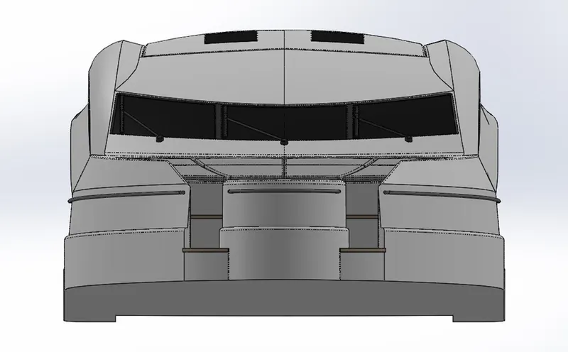
Front view.
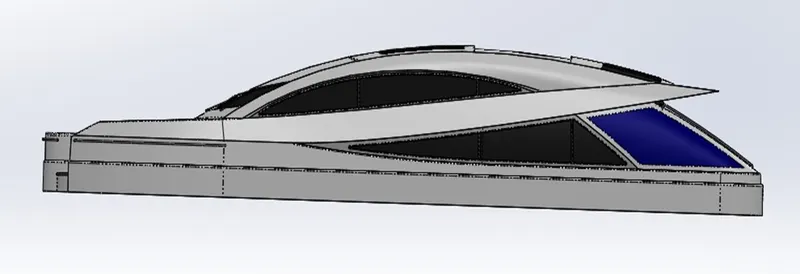
Side view.
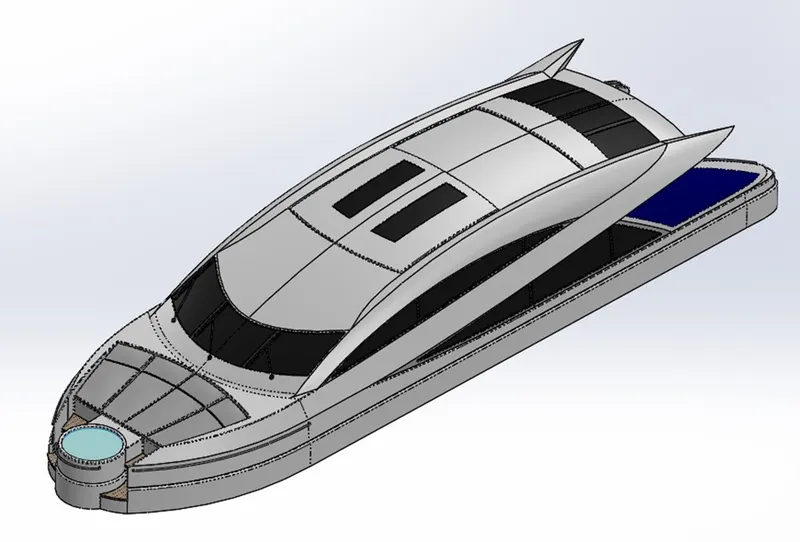
Isometric view of superstructure shown in the above picture.
- Radar Mast:
Radar mast is a electronic navigation instrument that use a rotating antenna to sweep a narrow beam of microwaves around the water surface surrounding the ship to the horizon, detecting targets by microwaves reflected from them, generating a picture of ship’s surroundings on a display screen. It is mounted over the superstructure of the yacht model.
- Creating sketches on the appropriate planes.
- Giving required dimensions to fully define the sketch.
- 3D parts created using these sketches.
- Shell is applied to the horns to form a funnel like structure or part.
- Fillets and chamfers are applied to the edges of the parts.
- Mirror applied to the bodies about the planes and faces of the parts to create a complete model.
- Domes created in the appropriate faces.
- Feature tools used: Reference plane, Extruded boss/base, Fillet, Revolved boss/base, Swept boss/base, Mirror, Projected curve, Chamfer, Dome & shell.
- Appearance: White, grey, light grey and some custom colours were applied to the parts.
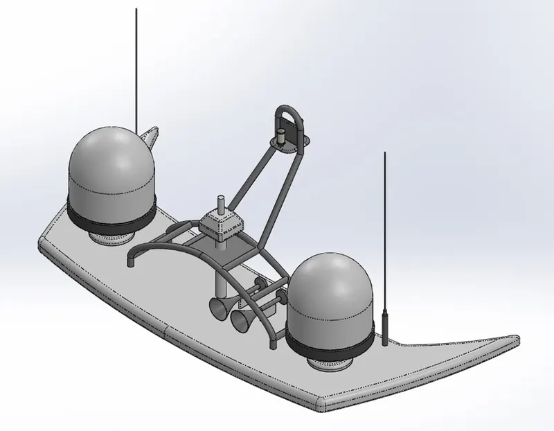
Isometric view of Radar mast shown in the above picture.
Assembly:
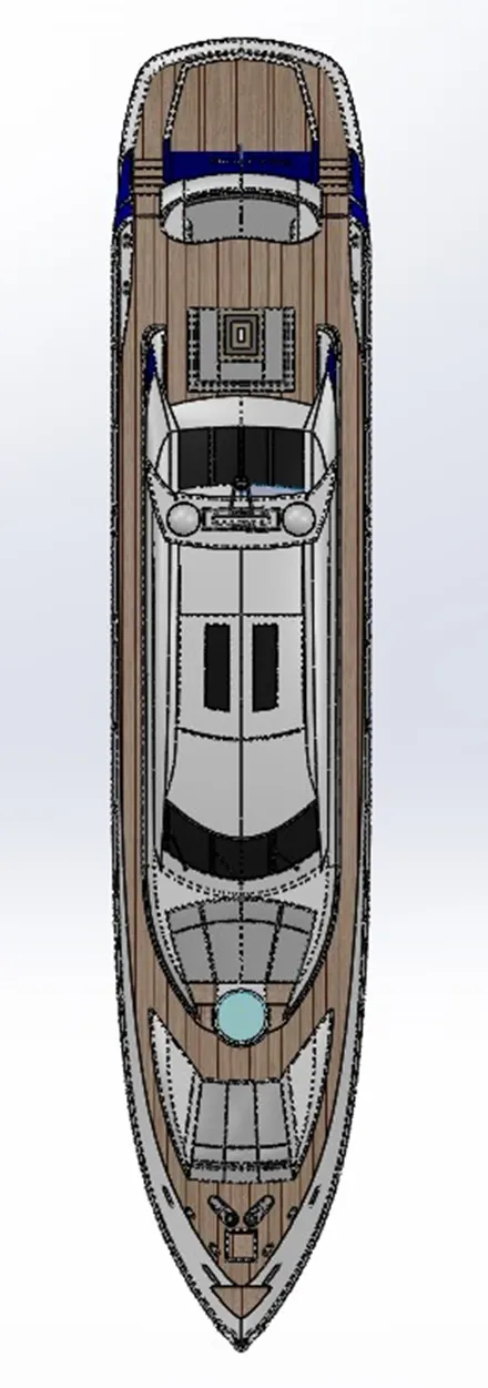
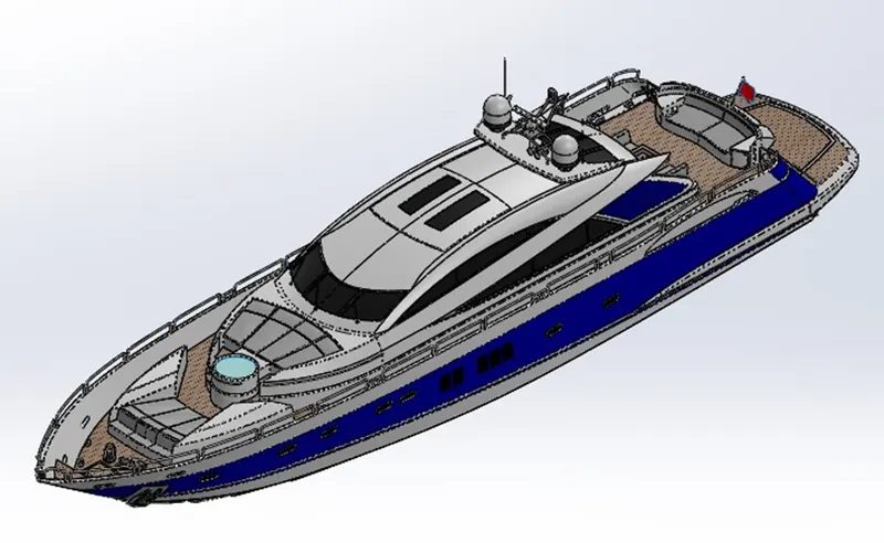
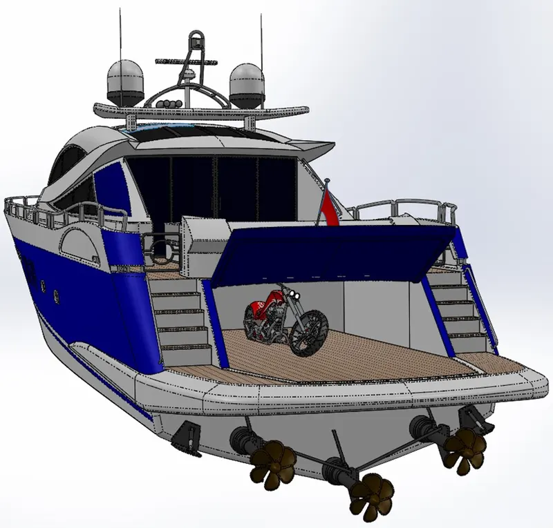
The previously designed parts are opened to assemble them by applying some mates to appropriate planes and geometry in the assembly window. In the yacht model some parts are created with reference to its previous parts surfaces to simplify the assembling of parts.
- First open the hull part in the assembly window and place it accordingly, to assemble other parts with reference to this part.
- Open the other parts one by one to the assembly window and apply some mates to the planes and geometry of the part to the Hull, the superstructure and the seat parts.
- Then fix the parts which are not fixed to avoid errors while assembling the other parts.
- Once all the parts are assembled apply some mates to the assembly plane and appropriate planes of parts.
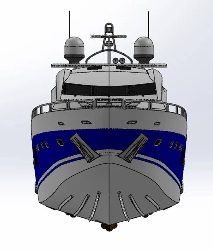
Front view.
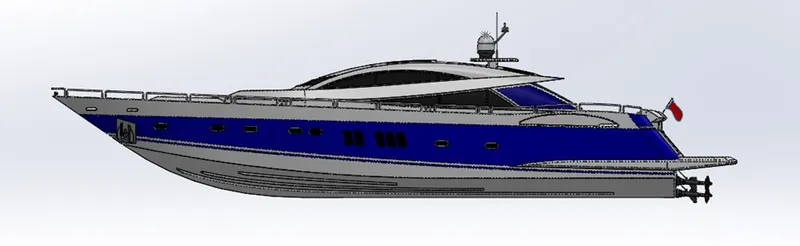
Side view.
Top view.
Isometric view.
Camera view.
Correcting the flaws in the assembly:
After assembling the parts, check for any flaws like parts over lapping. If any flaws were identified correct it, by changing the geometry of parts in the part level.
Final render:
Some lights and cameras are created in the render window with the help of photoview 360 feature in “SOLIDWORKS”, to highlight the design of Sunseeker predator yacht and then scenes & environments are set to the design for final render. This render showcases the realistic view of the design.
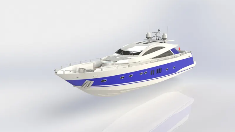
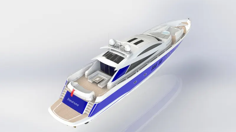
Final render of Sunseeker predator yacht shown in the above pictures.
Photo realistic rendering:
By using “SOLIDWORKS Visualize” rendering software, the appearance of the design changed and the real time ‘hdr’ scenes added as the environment to design. To make the design merged with this environment for photo realistic rendering.
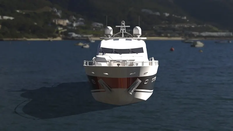
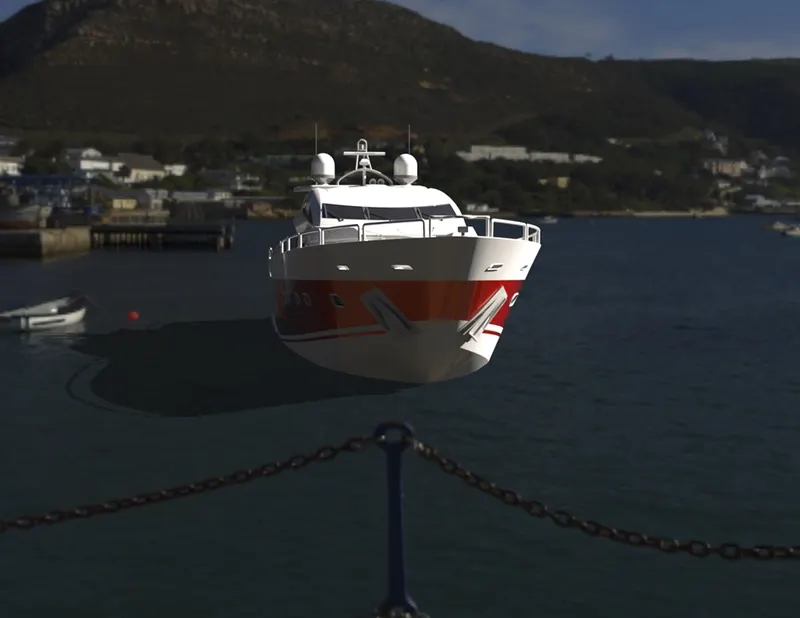
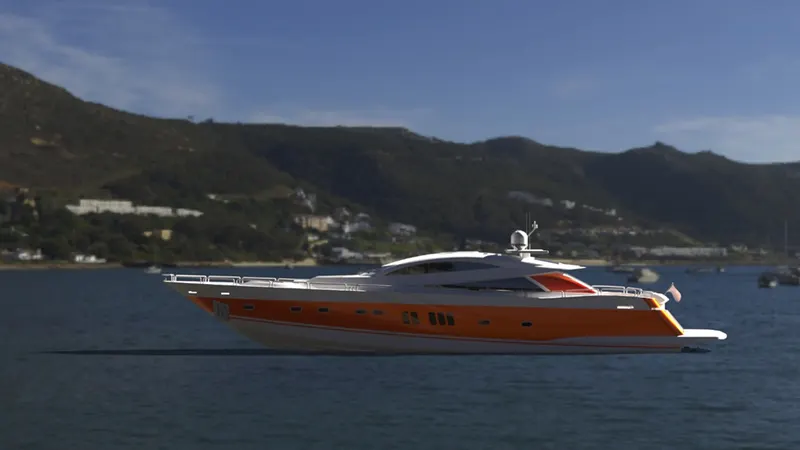
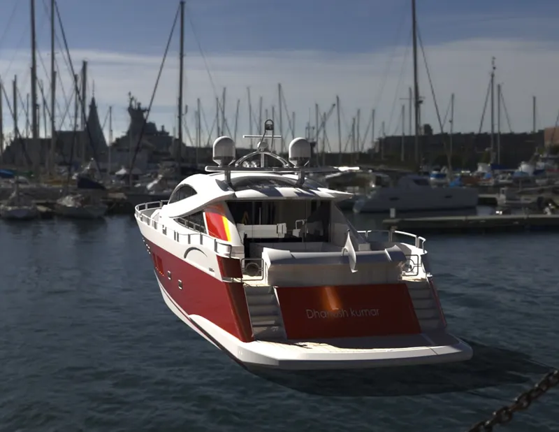
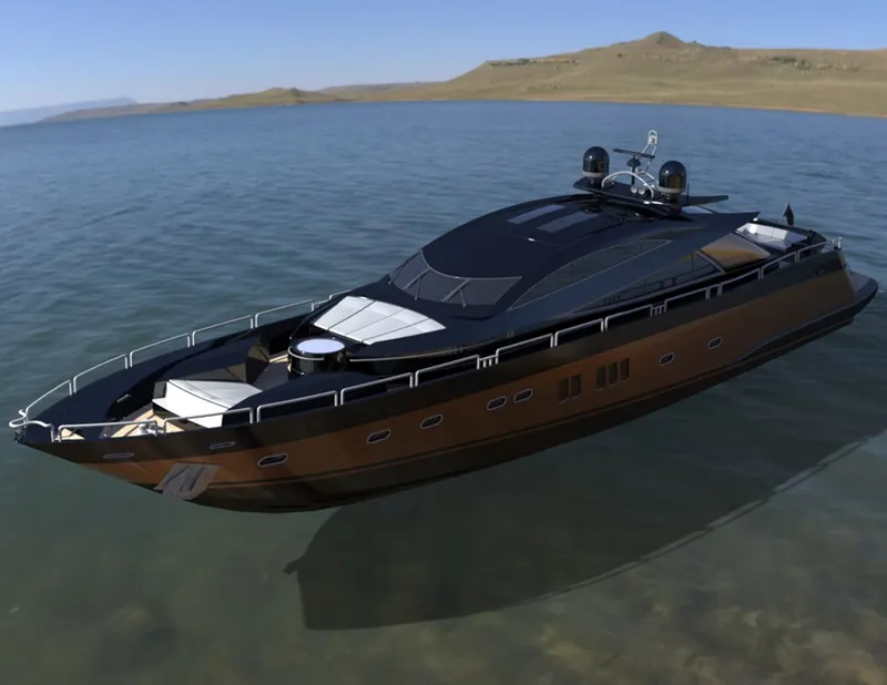
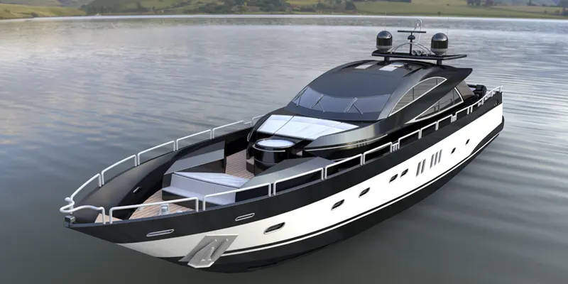
Photo realistic renders of the Sunseeker Predator yacht in different environments in various views are shown in the above pictures.
Conclusion:
Throughout this project, two software’s were mainly used to design the parts required for assembly of an Sunseeker Predator Yacht model and to render it. And the software’s are “SOLIDWORKS & SOLIDWORKS Visualize”. In this project a design was inspired from already available yacht models and the blueprint setup of a model is set to design the parts with required dimensions and features. Then the designed parts are assembled to form an Sunseeker Predator Yacht and its flaws are corrected. After this process, decals, lights and cameras are added to make the model more realistic to render. Then the appropriate environment is added as a background to the model to make photo realistic renders.