Designing of American Chopper Parts & its Assembly with Photo Realistic Rendering using – “SOLIDWORKS and SOLIDWORKS Visualize”.
Designing of American Chopper Parts & its Assembly with Photo Realistic Rendering using – “SOLIDWORKS and SOLIDWORKS Visualize”.
Objective:
To design a American Chopper from concept sketch to fully defined model for final rendering with my interests towards design and to develop my skills in design to next level using – “SOLIDWORKS and SOLIDWORKS Visualize” software.
Introduction:
This report is fully about how an American Chopper (Chopper is a type of custom motorcycle which emerged in the late 1950s) designed from,
-
-
- Scratch to concept sketch inspired from mood board.
- Concept sketch to designing of parts with appropriate dimensions.
- Adding appearance to the parts.
- Assembling the parts designed by using - “SOLIDWORKS”.
- Correcting the flaws in the assembled model.
- Final render of American Chopper.
- Photo Realistic Rendering using - “SOLIDWORKS Visualize”.
-
Process plan for Design:
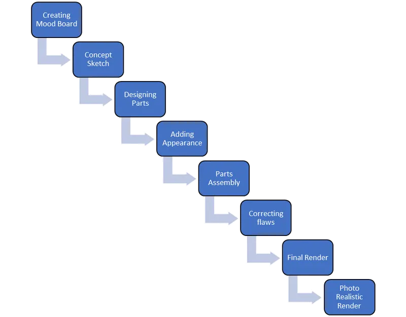
Mood Board: A type of visual presentation or ‘collage’ consisting of images, text, and samples of objects in a composition for design inspiration.
Concept Sketch: A rough representation of a model drawn often in freehand.
Parts to Design:
-
-
- Transmission Belt
- Kickstand
- Front Fender
- Rear Fender
- Chain
- Oil Tank
- Pedal
- Front Wheel
- Rear Wheel
- Front Fork
- Chassis
- Engine
- Gas Tank.
-
Feature and Surface Tools used:
|
: |
This feature will allow you to take a 2D sketch and add thickness to it in the third dimension. |
|
: |
This feature will allow you to remove material from the part by projecting a sketch section normal to the sketching plane. |
|
: |
It is used to create solid 3D model around an axis |
|
: |
Revolved cut is one of the very useful feature tool, which helps to remove materials from 3D models possess axis symmetry or removes material by revolving a closed profile along an axis. |
|
: |
This feature tool is helps to create 3D product design parts by sweeping. Some of the application examples are create spring model, complex hollow pipes, air conditioning ducts, curved rods, tubes, twisted parts, etc… |
|
: |
It is mainly used to cut a solid model or part by sweeping a completely closed profile along on open or closed path. |
|
: |
Mainly helps to add materials between two or more profiles with ease. |
|
: |
Fillet creates a rounded internal or external face on the part. It is mainly used on the edges and corners of faces or parts. |
|
: |
It creates a bevelled feature on selected edges, faces or a vertex. It is used to create sloped or angled edges. |
|
: |
Are used to create multiple instances of one or more features that you can space uniformly along one or two linear paths. |
|
: |
This feature helps to create multiple instances of one or more features that you can space uniformly around an axis. |
|
: |
It allows you to create patterns along a planar or 3D curve. |
|
: |
This command creates a copy of a feature, (or multiple features), mirrored about a face or a plane. |
|
: |
It is used to create a hollow space within a solid part according to its thickness value given, mainly used in tank designs. |
|
: |
It helps to create projection of two sketch in different intersecting planes and this curve is used as a path for sweep. |
|
: |
It allows you to combine curves, sketch geometry and model edges into a single curve and this created curve is used as a guide curve for creating a loft or a sweep. |
|
: |
This tool projects an entity (sketch, solid, surface, face, plane, or surface spline) to surface, or curved or planar faces. |
|
: |
It helps to create a plane within the sketches and it is added to facilitate an extruded cut on a non-planar face. |
|
: |
It creates a hollow half sphere that is tangent to the adjacent cylindrical or conical face. |
|
: |
This feature helps to create multiple parts from an existing part (or) you can split one or more solid or surface bodies. |
|
: |
It allows you to add two bodies together, and keep the area that is common to them. |
|
: |
You can move, rotate, and copy – solid and surface bodies, or place them using mates with the help of this feature tool. |
|
: |
It helps to create surfaces with a smooth tangency between the selected curves by multiple 3D curves or existing edges. |
|
: |
This tool is used to combine two or more faces and surfaces into one. |
- Transmission Belt:
Transmission belt is a loop of flexible material used to link two or more rotating shafts mechanically, most often parallel. It is used as a source of motion, to transmit power efficiently.
-
-
- The design of transmission belt is done by choosing appropriate planes in the “SOLIDWORKS” work window to create some 2D sketches.
- Then using the feature tools 2D sketches are extruded to 3D part.
- After creating part, fillet applied to its edges.
- Sketch tools used: Line, arc, offset and smart dimension.
- Feature tools used: Extruded boss/base & Fillet.
- Appearance: Matt Rubber appearance applied to the part.
-
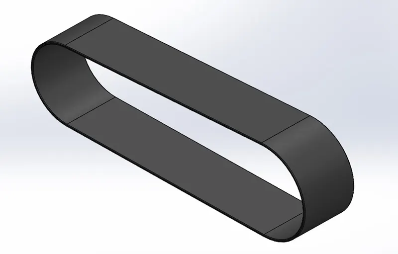
Isometric view of transmission belt is shown in the above picture.
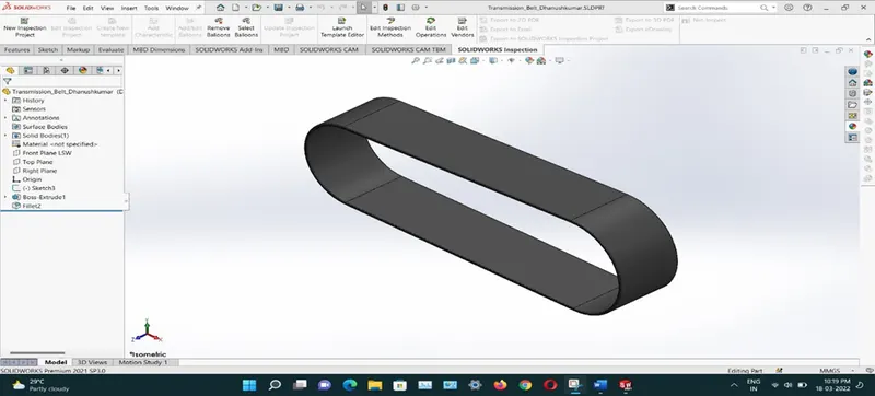
“SOLIDWORKS” work window sample shown in the above picture.
- Kickstand:
Kickstand is a device on a bicycle or motorcycle that allows the bike to be kept upright without leaning against another object or the aid of a person.
-
-
- Choosing the appropriate planes and rename the planes accordingly.
- Creating new sketches on these planes.
- Giving required dimensions to fully define the sketch.
- With the help of feature tools 3D part created based on the sketch drawn previously.
- After the part creation a cut made at the large end for mounting space, then fillet applied to edges and a dome created at the small end.
- Sketch tools used: Line, construction line, ellipse and spline.
- Feature tools used: Lofted boss/base, Dome, Extruded cut, Split, Extruded boss/base & Fillet.
- Appearance: Chrome plate appearance applied to the part.
-
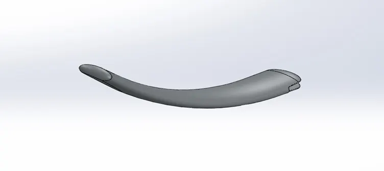
Isometric view of kickstand shown in the above picture.
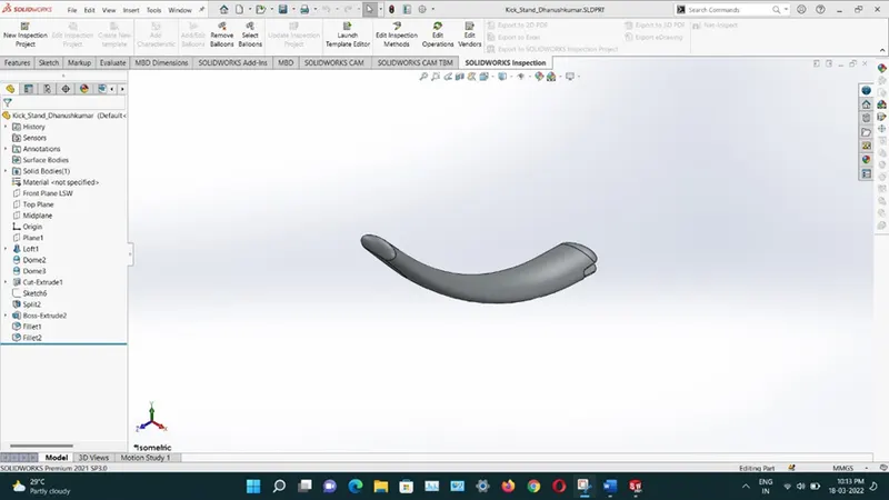
“SOLIDWORKS” work window sample shown in the above picture.
- Front Fender:
Front fender forms the barrier between the flying dirt and the upper part of the bike while moving. This structure is usually attached to the lower body of bike and placed two-inch above the front wheel.
-
-
- Choosing the appropriate planes and rename the planes accordingly.
- Creating sketches on these planes.
- Giving required dimensions to fully define the sketch.
- With the help of feature tools 3D part created based on the sketch drawn previously and then fillet applied to the edges of this part.
- Sketch tools used: Line, construction line, 3-point arc, spline, offset, trim & extend entity.
- Feature tools used: Revolved boss/base, Mirror entities, Split & Fillet.
- Appearance: Candy apple red appearance applied to this part.
-
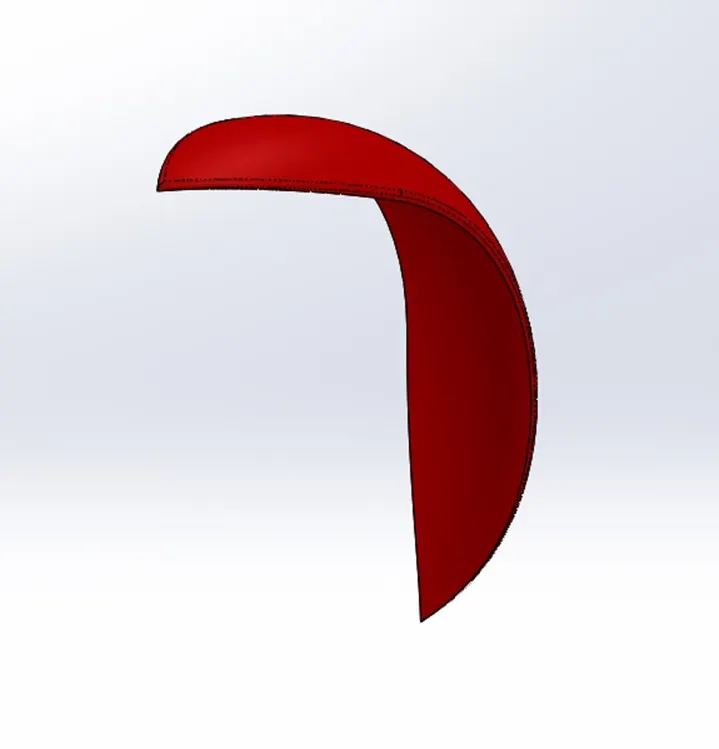
Isometric view of Front fender shown in the above picture.
- Rear Fender:
Rear fender forms the barrier between the flying dirt and the upper part of the bike while moving. This structure is usually attached to the lower body of bike and placed two-inch above the rear wheel.
-
-
- Choosing the appropriate planes and rename the planes accordingly.
- Creating sketches on these planes.
- Giving required dimensions to fully define the sketch.
- With the help of feature tools 3D part created based on the sketch drawn previously and then fillet applied to the part edges.
- Sketch tools used: Line, construction line, 3-point arc, spline, offset, trim & extend entity.
- Feature tools used: Revolved boss/base, Mirror entities, Shell, Split & Fillet.
- Appearance: Candy apple red appearance applied to this part.
-
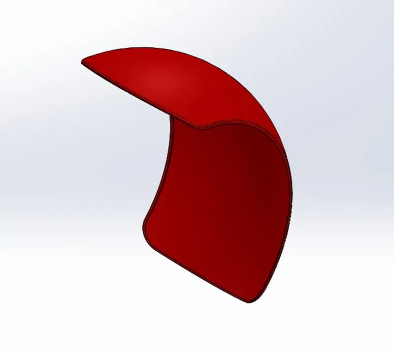
Isometric view of Rear fender shown in the above picture.
- Chain:
Chain is used to transfer power from the sprocket attached with the camshaft of engine to the sprocket in the rear wheel axle.
-
-
- Choosing the appropriate planes and rename the planes accordingly.
- Creating sketches on these planes.
- Giving required dimensions to fully define the sketch to create solid links.
- With the help of these solid links, curve driven pattern applied to form other links of chain.
- Once the links are created, then these are mirrored about the appropriate plane to form 3D part
- Sketch tools used: Line, construction line, arc, circle, offset, trim & extend entity.
- Feature tools used: Extruded boss/base, Mirror entities, Curve driven pattern & Fillet.
- Appearance: Chromium plate appearance applied to this part.
-
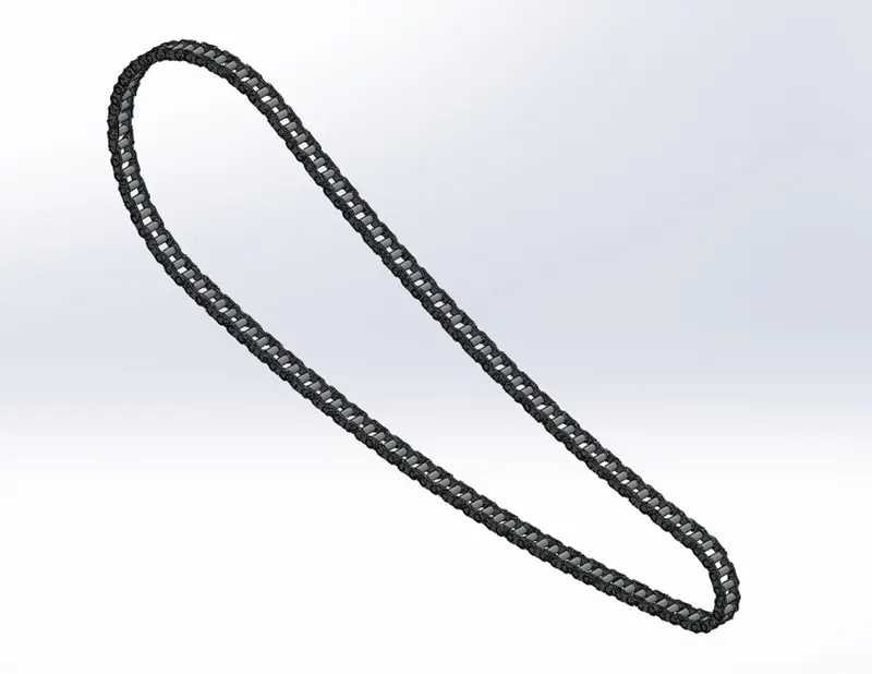
Isometric view of Chain shown in the above picture.
- Oil Tank:
Its purpose is to store oil which is necessary to minimise the friction in the moving parts of engine, while operating.
-
-
- Same procedure as before to create 3D parts from 2D sketches.
- After creating 3D part apply shell command to make it hollow in the inside of solid part to form shell like structure to store oil.
- Sketch tools used: Line, construction line, sketch point & spline.
- Feature tools used: Mirror, Extruded boss/base, Combine, Fillet & Shell.
- Appearance: Candy apple red appearance applied to the part & Metallic warm grey to the fillets.
-
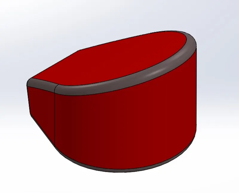
Isometric view of Oil tank shown in the above picture.
- Pedal:
Pedal is used as a support to the rider’s legs and it is mounted at both side of bike chassis.
-
-
- Same procedure as before for 3D part creation using 2D sketches.
- After creating part linear pattern applied at the desired faces.
- Then fillet, chamfer and dome created at the corresponding edges and faces.
- Sketch tools used: Line, construction line, spline & circle.
- Feature tools used: Extruded boss/base, Fillet, Revolved boss/base, Dome, Chamfer & Linear pattern.
- Appearance: Chromium plate appearance applied to this part.
-
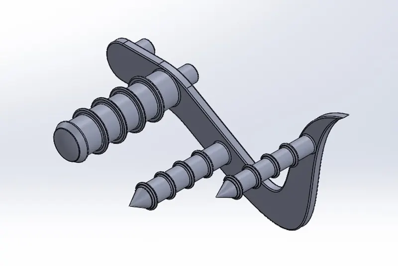
Isometric view of Pedal shown in the above picture.
- Front Wheel:
Front wheel is attached with the front fork of bikes with the help of axle between the fork tubes, to control the direction of the bike while operating. It has no contact with other parts of bike except fork and it works accordingly with acceleration given to engine.
-
-
- Same procedure as before to create solid parts.
- After creating the rim part, a spider webbed design is created between the rim and its centre.
- A brake rotor part is created then, with a brake calliper in it.
- Then a mounting space created at the centres.
- After creating rim, spokes, brake rotor & calliper some fillets and chamfers created in the required edges and faces.
- Over this solid part a tyre is created with some patterns for grip, at the outer face of the tyre.
- Sketch tools used: Line, construction line, spline, arc, circle & rectangle.
- Feature tools used: Revolved boss/base, Mirror, Extruded boss/base, Extruded cut, Revolved cut, Circular pattern, Combine, Fillet, Linear pattern & Chamfer.
- Appearance: Chromium plate for the rim and spokes, Carbon steel for the brake rotor, Candy apple red for the calliper and Matt rubber for the tyre.
-
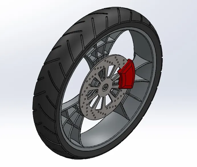
Isometric view.
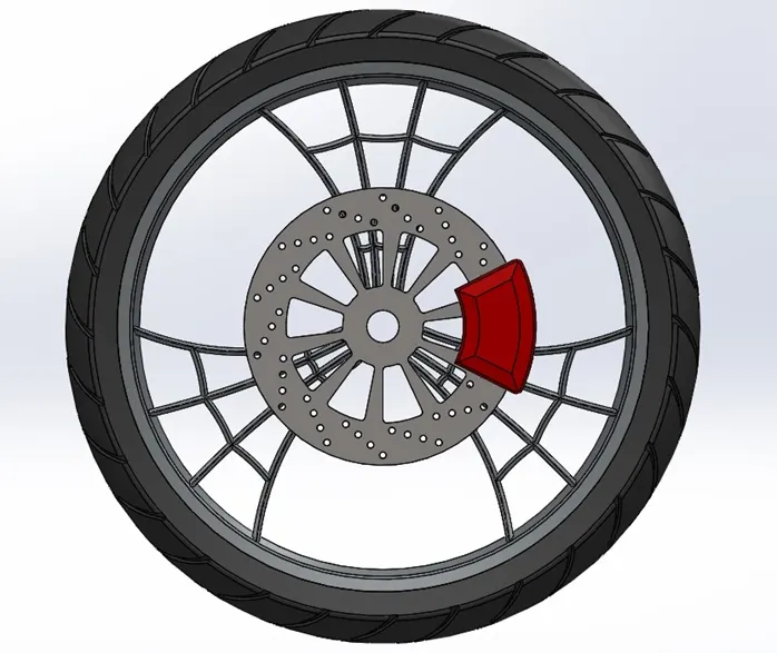
Side view.
- Rear Wheel:
Rear wheel is an important part in the bike, which receives power from the engine with the help of gear box, transmission belt and chain to operate the bike when acceleration is applied.
-
-
- Same procedure as before to create solid parts.
- After creating the rim part, a spider webbed design is created between the rim and its centre.
- A brake rotor part is created then, with a brake calliper in it.
- Then a mounting space created at the centres.
- After creating rim, spokes, brake rotor & calliper some fillets and chamfers created in the required edges and faces.
- Over this solid part a tyre is created with some patterns for grip, at the outer face of the tyre and a chain sprocket created parallel to the brake rotor.
- Sketch tools used: Line, construction line, spline, arc, circle & rectangle.
- Feature tools used: Revolved boss/base, Mirror, Extruded boss/base, Extruded cut, Revolved cut, Circular pattern, Combine, Fillet, Linear pattern & Chamfer.
- Appearance: Chromium plate for the rim and spokes, Carbon steel for the brake rotor, Candy apple red for the calliper and Matt rubber for the tyre.
-
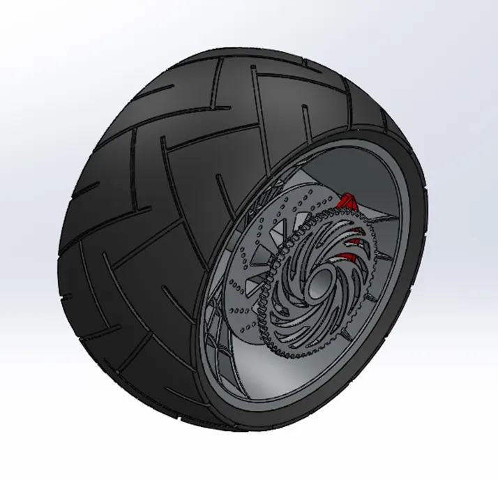
Isometric view.
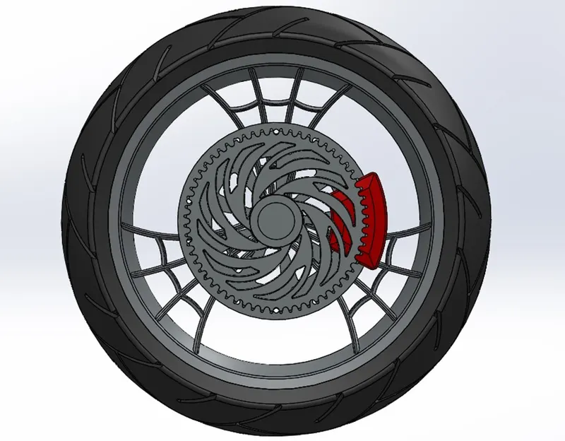
Side view.
- Front Fork:
It connects the front wheel and axle to the frame. It is also called as triple clamp.
-
-
- Same procedure as before for creating the fork tube.
- Then the triple clamps are created at the top end of fork tube to support the handle bar.
- Mirror applied to this part to form a copy about the face selected in the triple clamp.
- A bucket for the headlight, cables and brake levers created at the desired positions.
- Fillets and dome applied to the edges and faces.
- Sketch tools used: Line, construction line, spline, arc, circle, trim, offset and intersection curve.
- Feature tools used: Revolved boss/base, Extruded boss/base, Fillet, Linear pattern, Move/copy, Extruded cut, Dome, Revolved cut, Swept boss/base & Mirror.
- Appearance: chromium plate for the tubes, clamps & handle bars. Glossy rubber for hand grip and cables. Area light for lights.
-
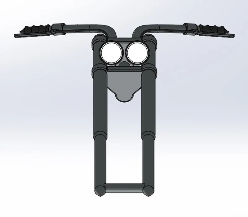
Fork front view.
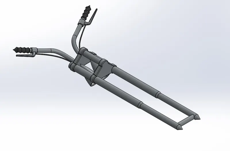
Isometric view.
- Chassis:
Chassis is a core structure. It supports engine, gas tank, seats and provides a location for the steering and rear suspension. It also supports the rider and passenger.
-
-
- Design procedure for chassis part is different, because of its curved structure.
- Starting with 2D sketches in the appropriate planes, then some features used to convert these sketches into a single sketch curve.
- With created curve, sweep applied along this path to form 3D part for the structure.
- Then a back plate created to support the curved 3D structure and the mounting plates created in the desired positions.
- Combined these parts to form a single solid part and fillets applied to the edges and in the joints.
- Sketch tools used: Line, construction line, spline, arc, circle and convert entities.
- Feature tools used: Project curve, Mirror, Extruded boss/ base, Extruded cut, Fillet, Chamfer, Swept boss/base, Dome, Split, Combine & Revolved boss/base.
- Appearance: Candy apple red appearance applied to chassis.
-
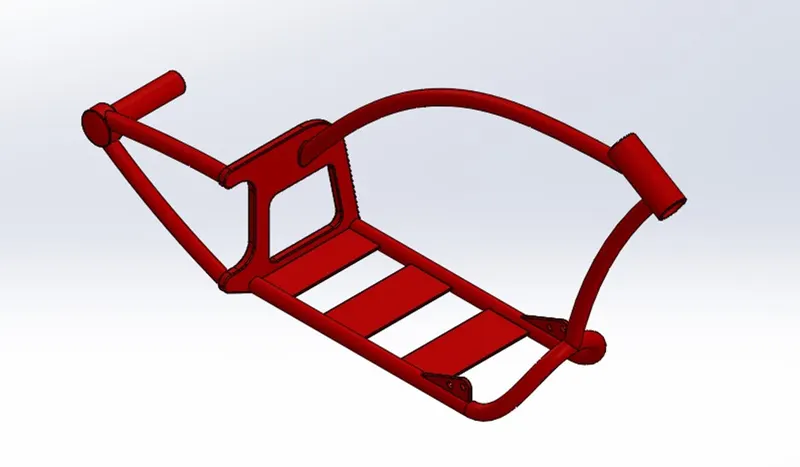
Isometric view of Chassis shown in the above picture.
- Engine:
An engine is a machine used to change energy into movement that can be transmitted to the wheels as power to operate the vehicle. It is also called as heart of vehicles.
-
-
- Engine design is the complex design, because of the parts associated with it.
- With the same procedure for creating 3D parts, first the casing for the engine is created.
- This casing is base for all other parts like cylinders, camshafts, fly wheels, etc…
- After creating the engine casing, cylinder parts are created in the top of casing and the fins are created in the cylinder outer faces.
- Then the exhaust tubes designed with some curves from the cylinders.
- At the cylinder heads, space for spark plugs created.
- Fillets and chamfers applied to the required edges & joints.
- Sketch tools used: Line, construction line, arc, spline, circle, trim, rectangle, offset, sketch fillet, convert entities & intersection curve.
- Feature tools used: Extruded boss/base, Fillet, Revolved boss/base, Circular pattern, Dome, Extruded cut, Chamfer, Split, Mirror, Swept boss/base, Combine, Project curve & Composite curve.
- Appearance: Chromium plate appearance applied to the engine.
-
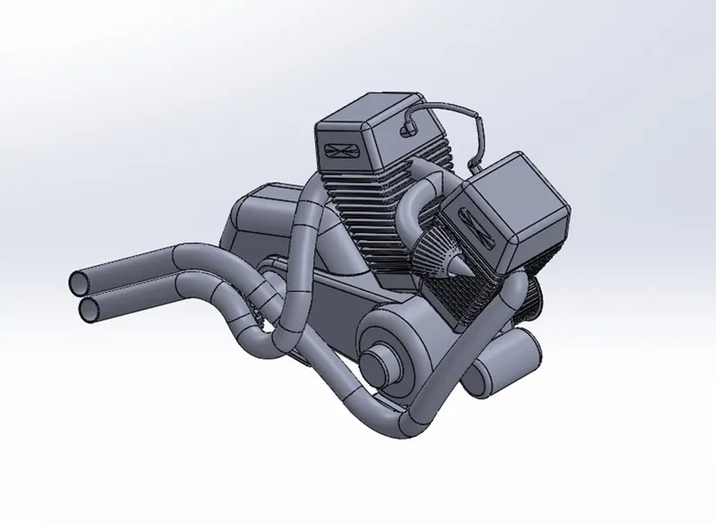
Isometric view of Engine shown in the above picture.
- Gas Tank:
It’s a storage unit for fuel required for the engine.
-
-
- Gas tank design is based on surface design.
- 2D sketches are drawn to make the surface of the tank part with the help of some feature tools.
- After creating the surface body, it then mirrored to form the top surface of the gas tank.
- And a seat is created in the desired position on the tank part.
- To complete the bottom surface of the tank part another feature tool is used and they were combined to form a single part.
- Shell command used to make hollow (or) to create vacuum space inside the tank part is applied and then the fillets at the required edges and joints.
- Sketch tools used: Line, construction line, arc, spline, circle, trim & convert entities.
- Feature tools used: Project curve, Lofted surface, Mirror, knit surface, Split line, Extruded surface, Fillet, Swept cut & Shell.
- Appearance: Candy apple red appearance applied to this part.
-
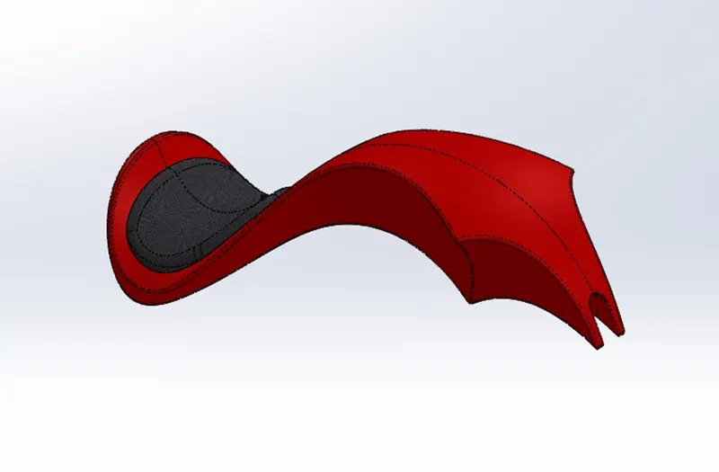
Isometric view.
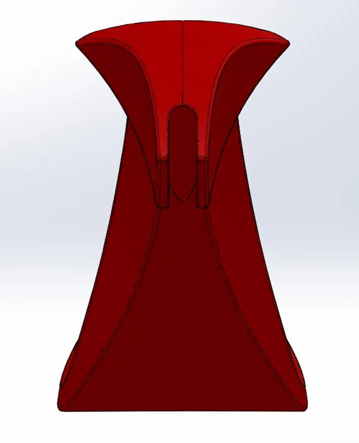
Side view.
Assembly:
The previously designed parts are opened to assemble them by applying mates to appropriate planes and geometry in the assembly window.
-
-
- First open the chassis part in the assembly window and place it accordingly, to assemble other parts with reference to chassis part.
- Open the other parts one by one to the assembly window and apply some mates to the planes and geometry of the part to the chassis part.
- Then fix the chassis part to avoid errors while assembling the other parts.
- Once all the parts are assembled apply some mates to the assembly plane and appropriate planes of parts.
-
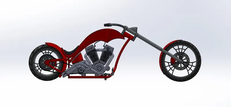
Front view.
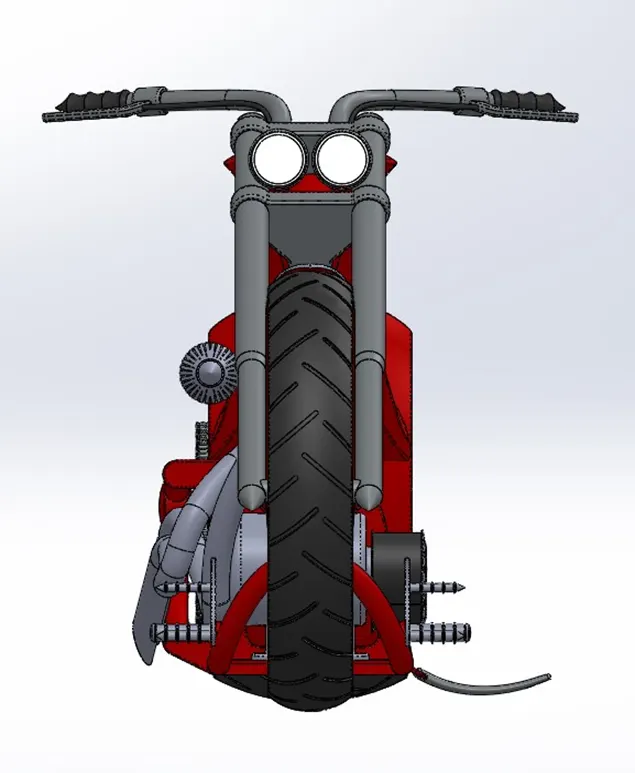
Side view.
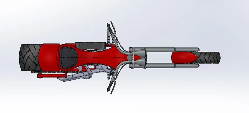
Top view.

Isometric view.
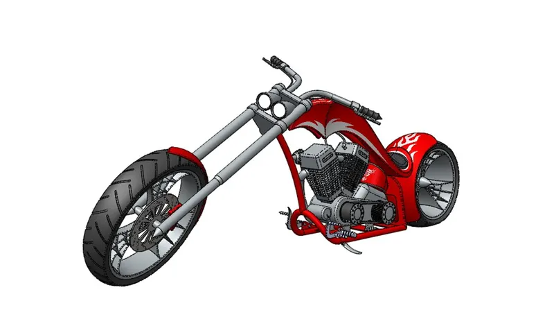
Camera view.
Correcting the flaws in the assembly:
After assembling the parts, check for any flaws like parts over lapping. If any flaws were identified correct it, by changing the geometry of parts in the part level.
Apply decals:
Decals are custom designed 2D patterns which are used apply on the surface of the parts, to make a visual treat.
-
-
- Some decals applied to front fender, rear fender, oil tank and gas tank to make the design to next level for visual treat.
-
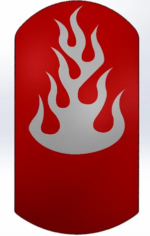
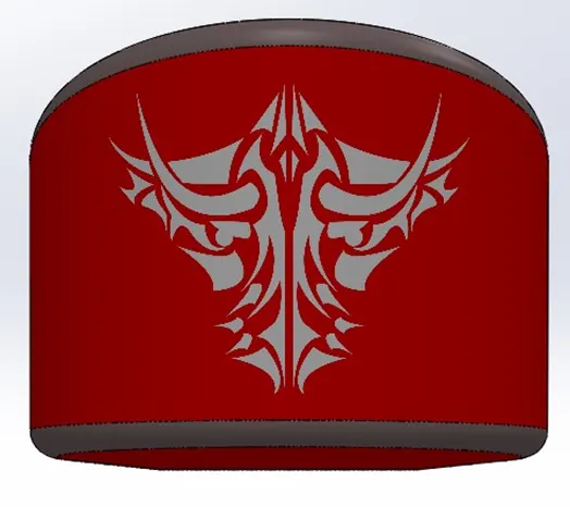
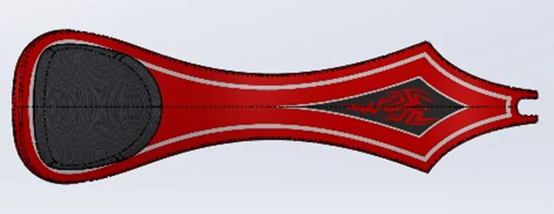
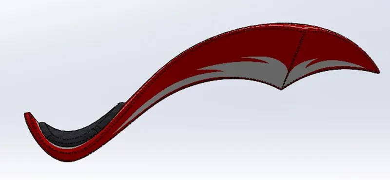
Decals applied parts pictures are shown above.
Final render:
Some lights and cameras are created in the render window with the help of photoview 360 feature in “SOLIDWORKS”, to highlight the design of American Chopper and then scenes & environments are set to the design for final render. This render showcases the realistic view of the design.
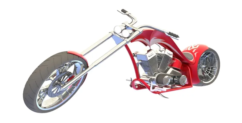
Final render of American Chopper shown in the above picture.
Photo realistic rendering:
By using “SOLIDWORKS Visualize” rendering software, the appearance of the design changed and the real time ‘hdr’ scenes added as the environment to design, to make the design merged with this environment for photo realistic rendering.
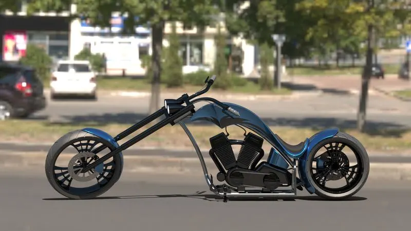
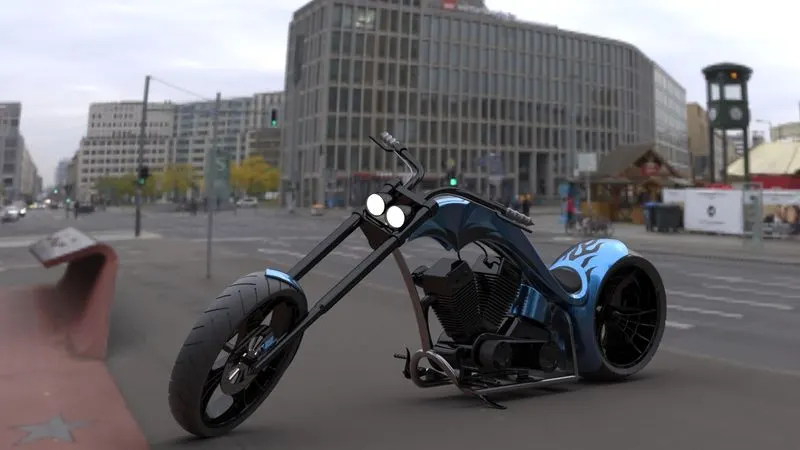
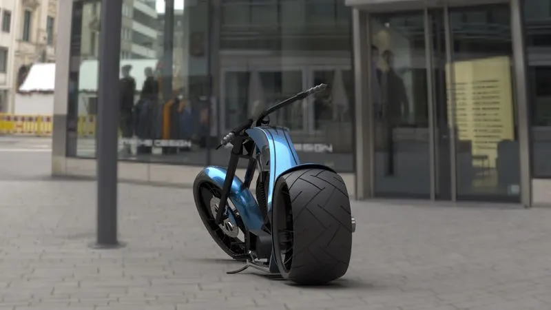
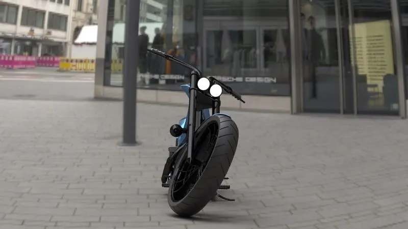
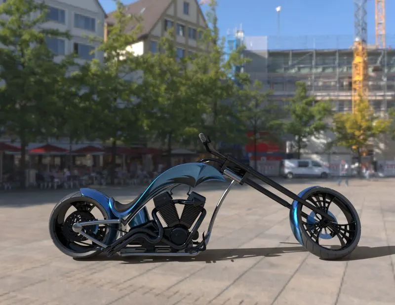
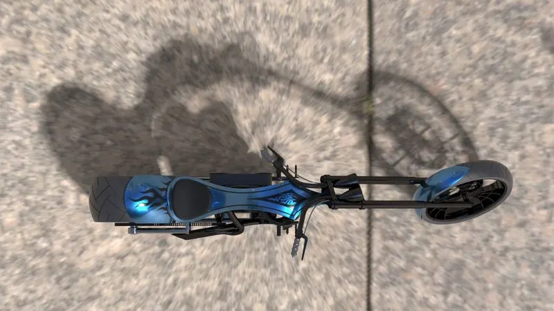
Photo realistic renders of the American Chopper in different environments in various views are shown in the above pictures.
Conclusion:
Throughout this project, two software’s are mainly used to design the parts required for assembly of an American Chopper model and to render it. And the software’s are “SOLIDWORKS & SOLIDWORKS Visualize”. In this project a design was inspired from the visual presentation to make a concept sketch of model to design the parts with required dimensions and features. Then the designed parts are assembled to form an American chopper and its flaws are corrected. After this process, decals, lights and cameras are added to make the model more realistic to render. Then the appropriate environment is added as a background to the model to make photo realistic render.