Surface Modelling of Lamborghini Aventador
Surface Modelling of Lamborghini Aventador, its Assembly, and Photo Realistic Rendering using – “SOLIDWORKS and SOLIDWORKS Visualize”.
Objective:
To design a surface model of Lamborghini Aventador from blueprint setup to fully defined model for final rendering with my interests towards design and to develop my skills in design using – “SOLIDWORKS and SOLIDWORKS Visualize” software.
Introduction:
This report is fully about how a Lamborghini Aventador (The Lamborghini Aventador is a mid-engine sportscar produced by the Italian automotive manufacturer Lamborghini.) designed from,
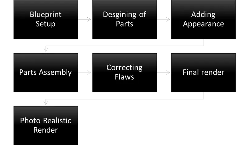
- Setting up the 2D images of Aventador model as base of reference for “Blueprint setup”.
- Blueprint setup to designing of parts with appropriate dimensions.
- Adding appearance to the parts.
- Assembling the parts designed by using - “SOLIDWORKS”.
- Correcting the flaws in the assembled model.
- Final render of Lamborghini Aventador.
- Photo Realistic Rendering using - “SOLIDWORKS Visualize”.
Process plan for Design:
Blueprint Setup: The different views of 2D images of already available Aventador model were placed in the appropriate planes to form a 3D base as a reference to design parts.
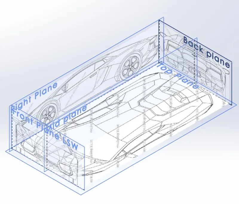
Isometric view of Blueprint setup shown in the above picture.
Parts to Design:
- Surface body
- Doors with Side Mirrors
- Hood/Bonnet
- Head Lamps
- Front Grille
- Middle Grille
- Rear/Tail Lamps
- Rear Grille
- Rear Bumper
- Rim
- Wheel hub
- Brake rotor
- Tyre
- Wiper Blades
Feature and Surface Tools used:
|
Ø Extruded Boss/Base |
: |
This feature will allow you to take a 2D sketch and add thickness to it in the third dimension. |
|
Ø Extruded Cut |
: |
This feature will allow you to remove material from the part by projecting a sketch section normal to the sketching plane. |
|
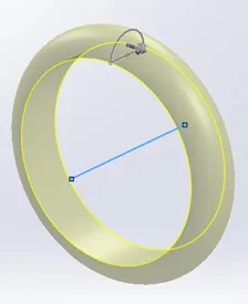
Ø Revolved Boss/Base |
: |
It is used to create solid 3D model around an axis. |
|
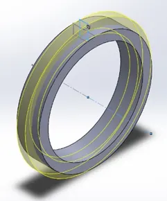
Ø Revolved cut |
: |
It helps to remove materials from 3D models posses axis symmetry or removes materials by revolving a closed profile along an axis. |
|
Ø Swept Boss/Base |
: |
This feature tool is helps to create 3D product design parts by sweeping. Some of the application examples are create spring model, complex hollow pipes, air conditioning ducts, curved rods, tubes, twisted parts, etc… |
|
Ø Lofted Boss/Base |
: |
Mainly helps to add materials between two or more profiles with ease. |
|
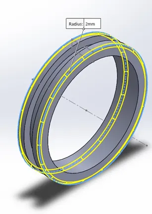
Ø Fillet |
: |
Fillet creates a rounded internal or external face on the part. It is mainly used on the edges and corners of faces or parts. |
|
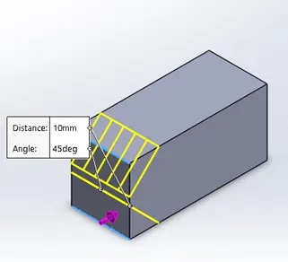
Ø Chamfer |
: |
It creates a bevelled feature on selected edges, faces or a vertex. It is used to create sloped or angled edges. |
|
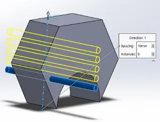
Ø Linear Pattern |
: |
Are used to create multiple instances of one or more features that you can space uniformly along one or two linear paths. |
|
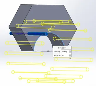
Ø Circular Pattern |
: |
This feature helps to create multiple instances of one or more features that you can space uniformly around an axis. |
|
Ø Fill Pattern |
: |
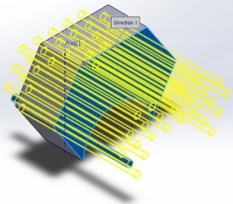
The fill pattern feature lets you select an area defined by co-planar faces or a sketch that lies on co-planar faces. This command fills the defined region with a pattern of features or a predefined cut shape. |
|
Ø Mirror |
: |
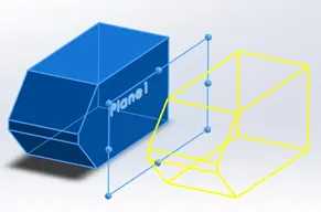
This command creates a copy of a feature, (or multiple features), mirrored about a face or a plane. |
|
Ø Project Curve |
: |
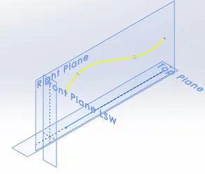
It helps to create projection of two sketch in different intersecting planes and this curve is used as a path for sweep. |
|
Ø Composite Curve |
: |
It allows you to combine curves, sketch geometry and model edges into a single curve and this created curve is used as a guide curve for creating a loft or a sweep. |
|
Ø Reference Plane |
: |
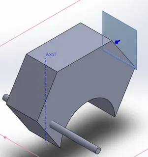
It helps to create a plane within the sketches and it is added to facilitate an extruded cut on a non-planar face. |
|
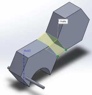
Ø Combine |
: |
It allows you to add two bodies together, and keep the area that is common to them. |
|
Ø Intersect |
: |
This feature is used to intersect solids, surfaces, or planes to modify existing geometry, or to create new geometry. For example, you can add open surface geometry to a solid, remove material from a model, or you can create geometry from an enclosed cavity. |
|
Ø Surface Extrude |
: |
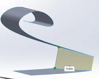
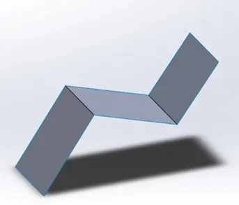
We can extrude the boundary edges of a face of a solid body or edges of a surface body in a customized direction by using this feature. |
|
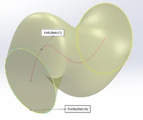
Ø Surface Sweep |
: |
Used to generate surfaces from a section curve positioned along a path. |
|
Ø Boundary Surface |
: |
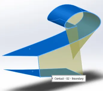
The boundary surface feature lets you create surfaces that can be tangent or curvature continuous in both directions (all sides of the surface). In most cases, this delivers a higher quality result than the loft tool. |
|
Ø Lofted Surface |
: |
It helps to create surfaces with a smooth tangency between the selected curves by multiple 3D curves or existing edges. |
|
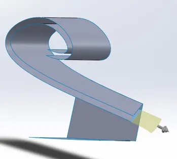
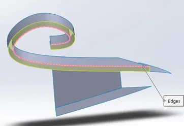
Ø Knit Surface |
: |
This tool is used to combine two or more faces and surfaces into one. |
|
Ø Surface Trim |
: |
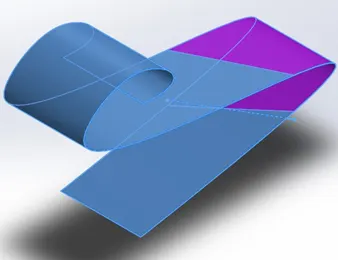
Used to trim the extra projection of surfaces which are intersecting or overlapping. |
|
Ø Surface Fill |
: |
The filled surface feature constructs a surface patch with any number of sides, within a boundary defined by existing model edges, sketches, or curves, including composite curves. |
|
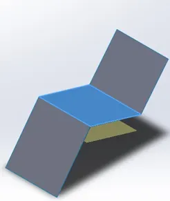
Ø Surface Extend |
: |
This feature helps to extend a surface by selecting an edge, multiple edges, or a face. |
|
Ø Ruled Surface |
: |
It creates surfaces that extend out in a specified direction from selected edges.
|
|
Ø Surface Offset |
: |
It creates a new surface body from an existing set of faces. |
|
Ø Body-move/copy |
: |
You can move, rotate, and copy solid and surface bodies, or place them using mates with the help of this feature. |
|
Ø Body-delete/keep |
: |
You can select bodies to keep or delete using the delete/keep body feature. This is useful in working with multibody parts with multiple configurations. |
|
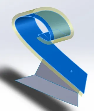
Ø Thicken |
: |
Creates a solid feature by thickening one or more adjacent surfaces. If the surface you want to thicken is made up of multiple adjacent surfaces, you must first knit the surfaces together before you thicken the surface. |
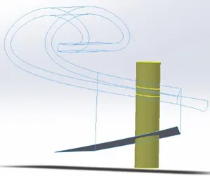
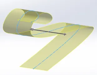
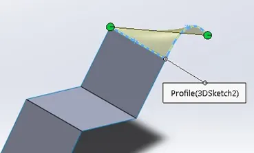
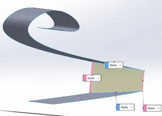
- Surface Body:
A Surface Body is the outer cover of the Automobiles placed over the chassis frame. It protects the driver and passengers from the direct sunlight and rain. It also separates the engine and other parts associated with it from the driver/passenger compartment. It consists of wind shield, hinges to doors, bonnet, engine cover and room for other external parts.
- The design of Surface body starts with some 2D sketches on planes with reference to the outlines in the blueprint setup.
- Then using the feature tools 2D sketches are converted to required curves and projections.
- Using these sketches 3D parts created by feature tools.
- These steps are repeated until the entire surface body created, like in the blueprint setup.
- During this some parts are inserted into the new part windows as a reference base for its associated parts like doors, engine cover, lights and grids.
- It helps to assemble the parts easily without any complications.
- The edges of the created parts are knitted together to fill the gaps and it creates a single part from the group of parts.
- After creating part, fillet applied to the required edges.
- Feature tools used: Boundary surface, Project curve, Extend surface, Composite curve, Trim surface, Extrude surface, Offset surface, Knit surface, Lofted surface, Swept surface, Filled surface, Fillet, Body-delete/keep, Reference plane, Intersect, Extruded boss/base, Extruded cut, Mirror, Split, Variable fillet, Body-move/copy, Lofted boss/base, Combine, Thicken and Swept boss/base.
- Appearance: White colour given to the surface body and some face appearances are changed to black thick gloss, black and dark grey colours.
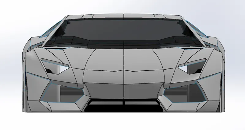
Front view.
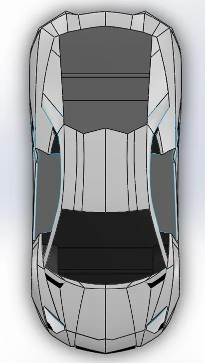
Top view.
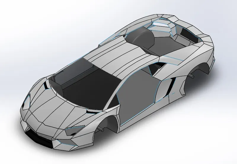
Isometric view of Surface body is shown in the above picture.
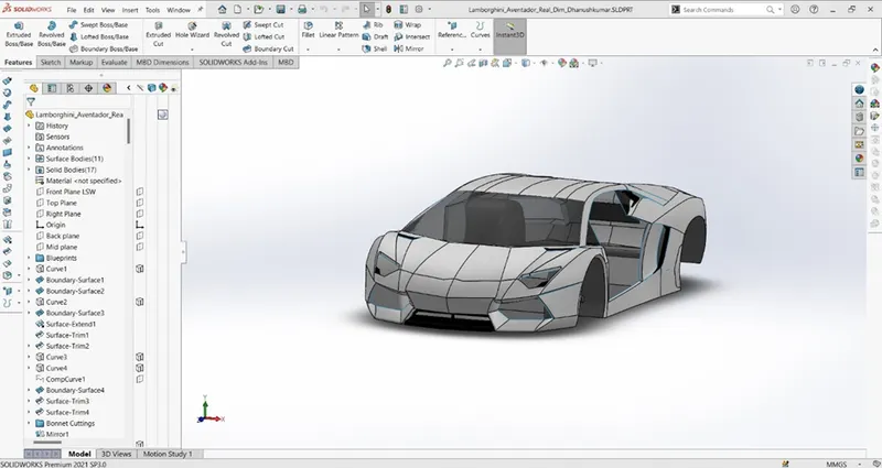
“SOLIDWORKS” work window sample shown in the above picture.
- Doors with Side Mirrors:
A car door is a type of door opening, typically hinged on its front edge, for entering and exiting a vehicle. Doors most often integrate side windows for visibility from inside the car and can be locked to secure the vehicle. In this model “Scissor doors” (also called flap doors, wing doors, beetle-wing doors, turtle doors, swing-up doors, and Lamborghini doors) are used. Scissor doors are automobile doors that rotate vertically at a fixed hinge at the front of the door, rather than outward as with a conventional door.
A side-view mirror (or side mirror), also known as a wing mirror, is a mirror placed on the exterior of motor vehicles for the purpose of helping the driver see areas behind and to the sides of the vehicles, outside the driver’s peripheral vision (in the “blind spot”). Almost all modern cars mount their side mirrors on the doors rather than the wings.
- Creating new sketches on the appropriate planes.
- Giving required dimensions to fully define the sketch.
- With the help of feature tools 3D part created based on the drawn 2D & 3D sketches.
- Some reference planes are created for designing the side mirror.
- Steps are repeated to form 3D parts and the overlapping of the solid and surface parts are intersected.
- Then knits and fillets are applied to the required edges.
- Feature tools used: Project curve, Swept surface, Intersect, Boundary surface, Lofted surface, Extruded surface, Trim surface, Reference plane, Thicken, Combine, Extended surface, Body-move/copy, Body-delete/keep, Mirror, Extruded boss/base, Lofted boss/base, Fillet, Offset surface, Knit surface and Extruded cut.
- Appearance: White colour applied to the part, Black thick gloss appearance given to the windows, black colour applied to side mirror covers & door handles and Reflective appearance given to the side mirrors.
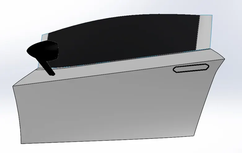
Side view.
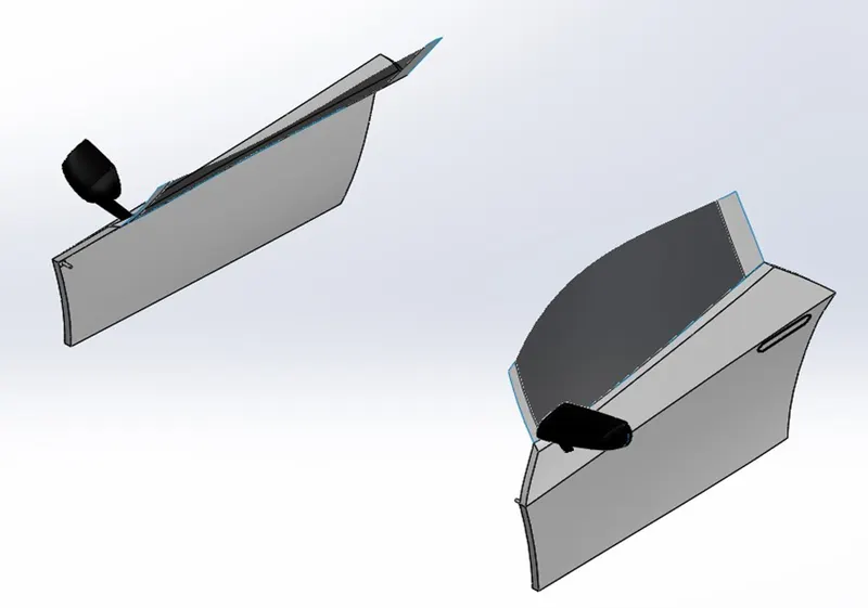
Isometric view of Doors with side mirrors shown in the above picture.
- Hood/Bonnet:
The hood or bonnet is the hinged cover over the engine of motor vehicles. Hood can open to allow access to the engine compartment, or trunk on rear-engine and some mid-engine vehicles for maintenance or repair.
- Creating sketches on the appropriate planes for tilted plates on the hood.
- Giving required dimensions to fully define the sketch.
- These plates give some room for air flow over the engine to cool it.
- After creating the parts, overlapping of solid and surfaces are intersected.
- Fillets were applied to the required edges.
- Feature tools used: Lofted surface, Boundary surface, Ruled surface, Trim surface, Extruded surface, Knit surface, Mirror, Reference plane, Extruded boss/base, Intersect and Extruded cut.
- Appearance: Black colour applied to the bonnet and black thick gloss applied to the centre plates.
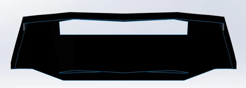
Front view.
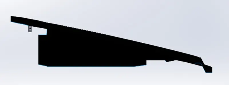
Side view.
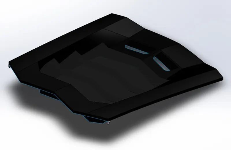
Isometric view of Hood/Bonnet shown in the above picture.
- Head Lamps:
A headlamp is a lamp attached to the front of a vehicle to illuminate the road ahead. Headlamps are also often called headlights, but in the most precise usage, headlamp is the term for the device itself and headlight is the term for the beam of light produced and distributed by the device.
- Creating sketches on appropriate planes.
- Giving required dimensions to fully define the sketch.
- With the help of feature tools and using the sketches 3D parts were created.
- Fillets were applied to the required edges and then mirror applied to the bodies & surfaces about midplane plane.
- Appearance and luminosity given to LED and its surrounding parts.
- Feature tools used: Swept surface, Trim surface, Lofted surface, Knit surface, Filled surface, Reference plane, Revolved boss/base, Extend surface, Extruded surface, Intersect and Mirror.
- Appearance: Black colour applied to the surface bodies, Light appearance given to the LED’s and white colour applied to the face for reflection pattern.
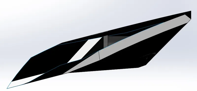
Side view.

Front view.
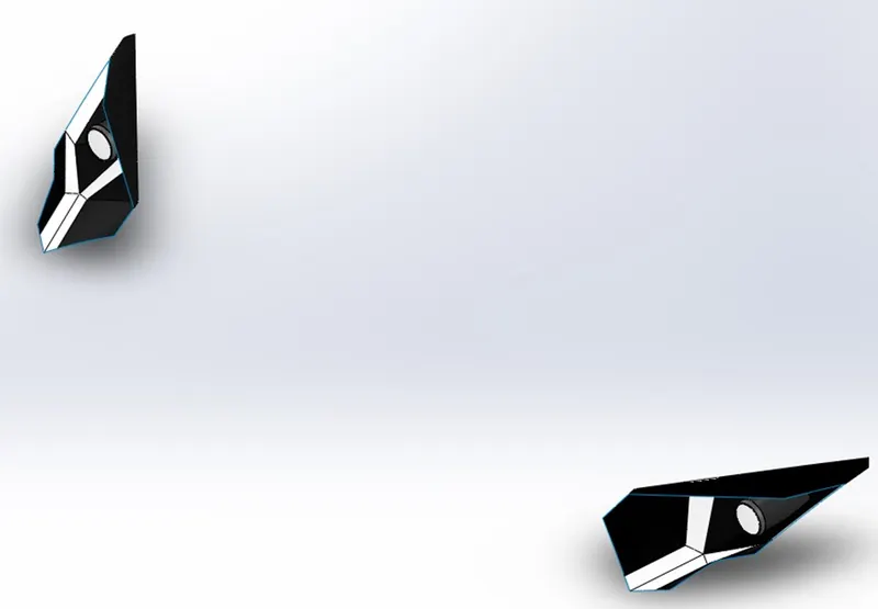
Isometric view.
- Front Grille:
A grille covers an opening in the body of a vehicle to allow air to enter or exit. Most vehicles feature a grille at the front of the vehicle to protect the radiator and engine. Common grille locations include below the front bumper, in front of the wheels (to cool the brakes), in the cowl for cabin ventilation, or on the rear deck lid (in rear engine vehicles).
- Creating sketches on the appropriate planes.
- Giving required dimensions to fully define the sketch.
- 3D Surfaces created using the defined sketches.
- Hexagon/Honeycomb like patterns were drawn and created to form the grille.
- These patterns are repeated to complete the grille.
- Then the extra projection & overlapping geometry were trimmed.
- These parts were merged/combined to form a single part.
- Fillets and Chamfers were applied to the required edges.
- Mirror applied about the mod plane of the part to complete the model.
- Feature tools used: Reference plane, Lofted surface, Offset surface, Trim surface, Extend surface, Ruled surface, Body-move/copy, Extruded boss/bass, Linear pattern, Combine, Extruded cut, Intersect, Body-delete/keep, Thicken, Fillet and Mirror.
- Appearance: Black colour applied to the pattern & outer surfaces and grey colour applied to the surface behind the pattern.
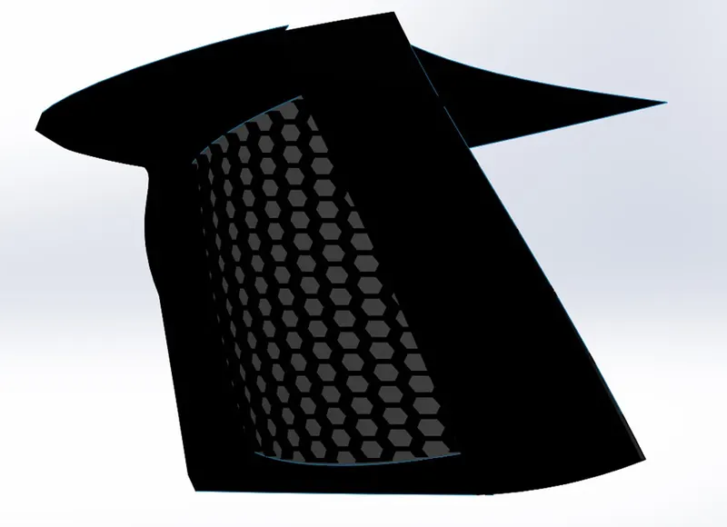
Side view.
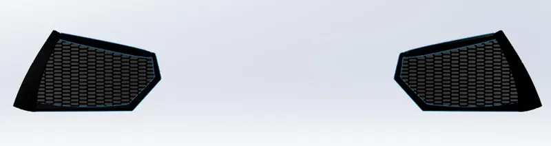
Front view.
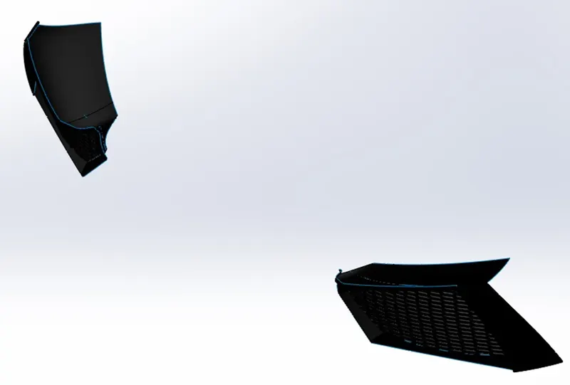
Isometric view of Front grille shown in the above picture.
- Middle Grille:
This grille is placed before the rear wheel at the body.
- Creating sketches on the appropriate planes.
- Giving required dimensions to fully define the sketch.
- 3D parts created using the defined sketches.
- Honeycomb pattern created and repeated to complete the part.
- Mirror applied about the mid plane of the part.
- Feature tools used: Reference plane, Thicken, Extruded boss/base, Fill pattern, Combine, Extruded cut, Knit surface, Body-move/copy and Mirror.
- Appearance: Black colour applied to the part.
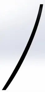
Side view.
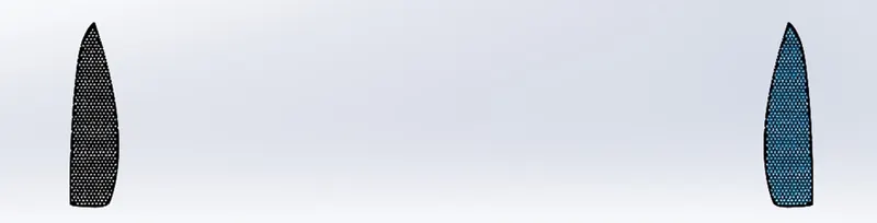
Front view of Middle grille shown in the above picture.
- Rear Grille:
Rear grille placed at the backside of the body and above the rear bumper.
- Creating sketches on the appropriate planes.
- Giving required dimensions to fully define the sketch.
- 3D Surfaces created using the defined sketches.
- Hexagon/Honeycomb like patterns were drawn and created to form the grille.
- These patterns are repeated to complete the grille.
- Then the extra projection & overlapping geometry were trimmed.
- These parts were merged/combined to form a single part.
- Fillets and Chamfers were applied to the required edges.
- Mirror applied about the mod plane of the part to complete the model.
- Feature tools used: Lofted surface, Knit surface, Offset surface, Reference plane, Extruded boss/base, Linear pattern, Combine, Intersect, Extruded cut, Body-delete/keep, Extend surface, Thicken and Mirror.
- Appearance: Black colour applied to the pattern & outer solid body and grey colour applied to the surface behind the pattern.

Back view.
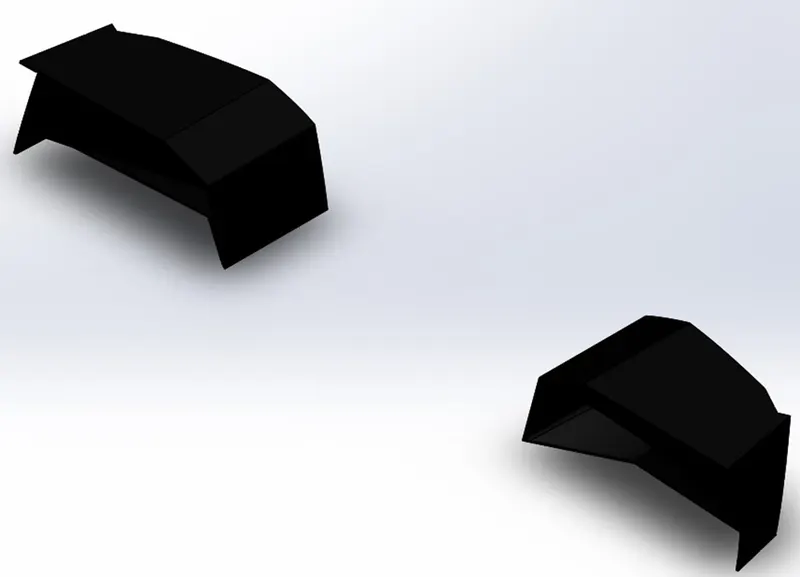
Isometric view of Rear grille shown in the above picture.
- Rear/Tail Lamps:
The rear/tail lamps are signalling device mounted or integrated at the rear side of vehicles. It allowing other drivers and pedestrians to see its presence, position, size, and direction of travel, and its driver’s intentions.
- Creating sketches on the appropriate planes.
- Giving required dimensions to fully define the sketch.
- 3D parts created using the defined sketches.
- The extra projections and overlapping of the surfaces were trimmed.
- These parts and surfaces are combined, then mirrored about the mid plane.
- Fillets were applied to the required edges.
- Feature tools used: Offset surface, Extend surface, Trim surface, Reference plane, Extruded boss/base, Fillet, Extruded surface, Lofted surface, Knit surface and Mirror.
- Appearance: Red light appearance applied to LED’s, Acrylic plastic appearance applied to outer surface and Black colour applied to surface behind LED’s.

Back view.
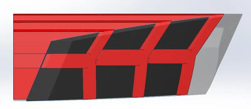
Side view.
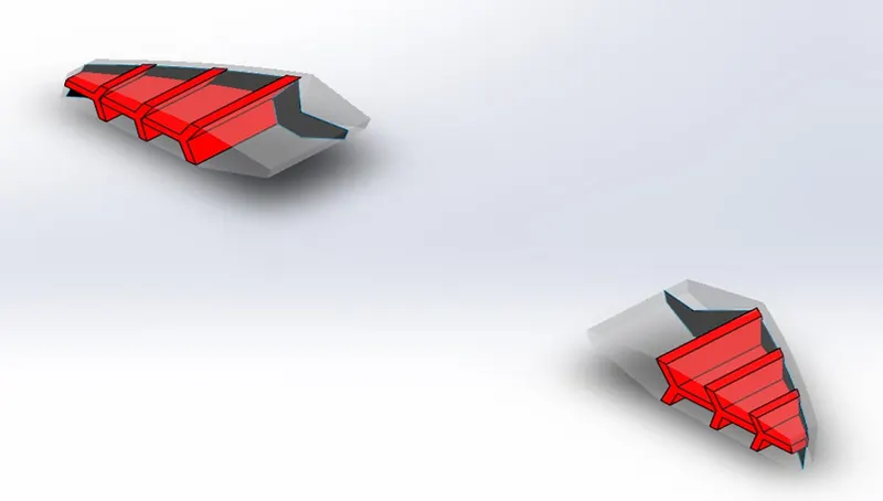
Isometric view of Rear/Tail lamps shown in the above picture.
- Rear Bumper:
A bumper is a structure attached to or integrated with the front and rear ends of a motor vehicle, to absorb impact in a minor collision, ideally minimizing the repairing costs.
- Creating sketches on the appropriate planes.
- Giving required dimensions to fully define the sketch.
- 3D parts created using the defined sketches.
- The extra projections and overlapping of the surfaces were trimmed.
- These parts are combined to form a single part.
- Fillets were applied to the required edges.
- Feature tools used: Extruded boss/base, Extruded surface, Body-move/copy, Offset surface, Intersect, Body-delete/keep, Extruded cut, Combine, Fillet.
- Appearance: Black colour applied to this whole part.

Back view.
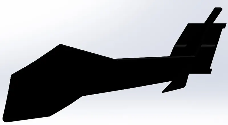
Side view.
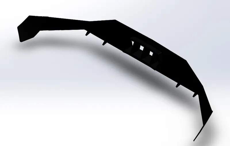
Isometric view.
- Rim:
The rim is the “outer edge of a wheel, holding the tire”. It makes up the outer circular design of the wheel on which the inside edge of the tire is mounted on vehicles such as automobiles.
- Creating sketches on the appropriate planes to form the outer rim.
- Giving required dimensions to fully define the sketch.
- 3D part created using the defined sketches.
- With reference to the outer rim, sketches were created to form spokes.
- These parts are combined to make it as a single part.
- Fillets were applied to the required edges.
- Feature tools used: Revolved boss/base, Extruded cut, Variable fillet, Fillet, Circular pattern, Combine, Lofted surface, Project curve, Swept surface, Knit surface, Trim surface, Extruded surface and Offset surface.
- Appearance: Black colour applied to the outer surface of rim & to the spokes and Grey colour applied to the surfaces between the spokes.
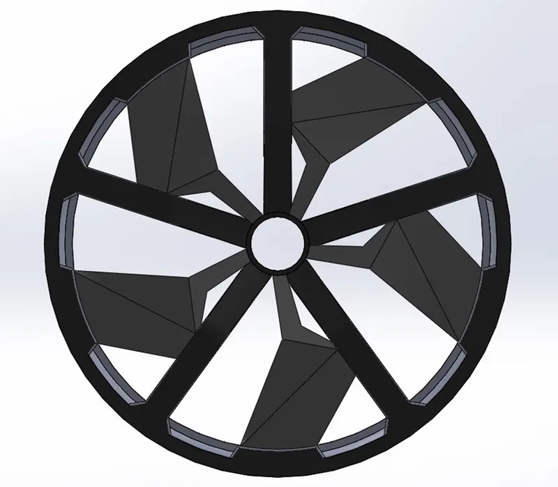
Front view.
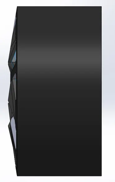
Side view.
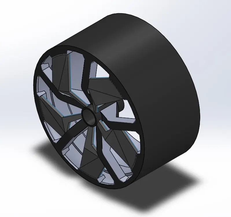
Isometric view.
- Wheel Hub:
Wheel hub are the centre region of the wheels holding the spokes from rim and makes contact with the axles to transfer motion from the differentials to the wheels.
- Creating sketches on the appropriate planes.
- Giving required dimensions to fully define the sketch.
- 3D part created using the defined sketches.
- Some cuts and patterns were applied to the part to complete its look.
- Feature tools used: Revolved boss/base, Extruded cut and Circular pattern.
- Appearance: Candy apple red applied to the part and black colour applied to the face at the centre of hub.
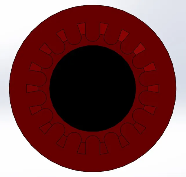
Front view.
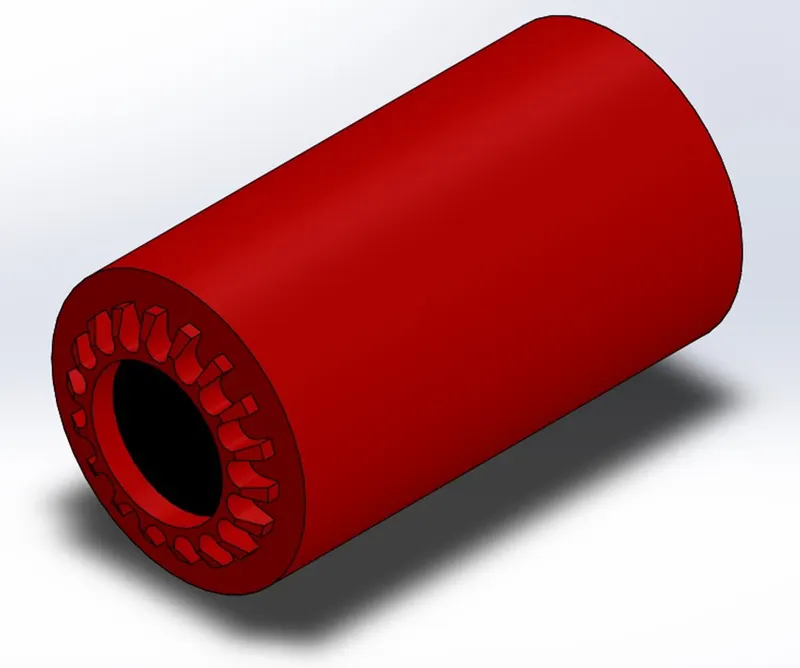
Isometric view.
- Brake Rotor:
Brake rotor is a metal disc with callipers act as a brake system to stop the vehicles from moving and to hold it stationary. This disc has several patterns in it to disperse the heat produced during braking by the friction created between the callipers and the disc/rotor.
- Creating sketches on the appropriate planes.
- Giving required dimensions to fully define the sketch.
- 3D parts created using the defined sketches.
- Then some cuts made on the disc with some patterns.
- With reference of the disc faces sketches made on it for the calliper part.
- Fillets were applied to the required edges.
- Feature tools used: Revolved boss/base, Extruded boss/base, Extruded cut and Fillet.
- Appearance: Candy apple red applied to the calliper and grey colour applied to the Rotor part.
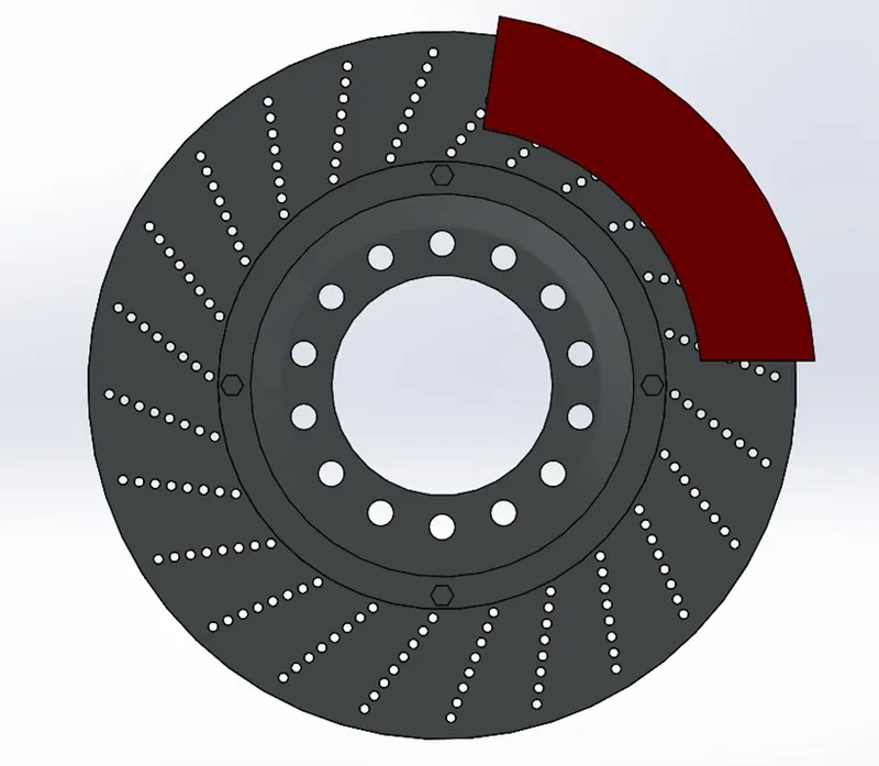
Front view.

Side view.
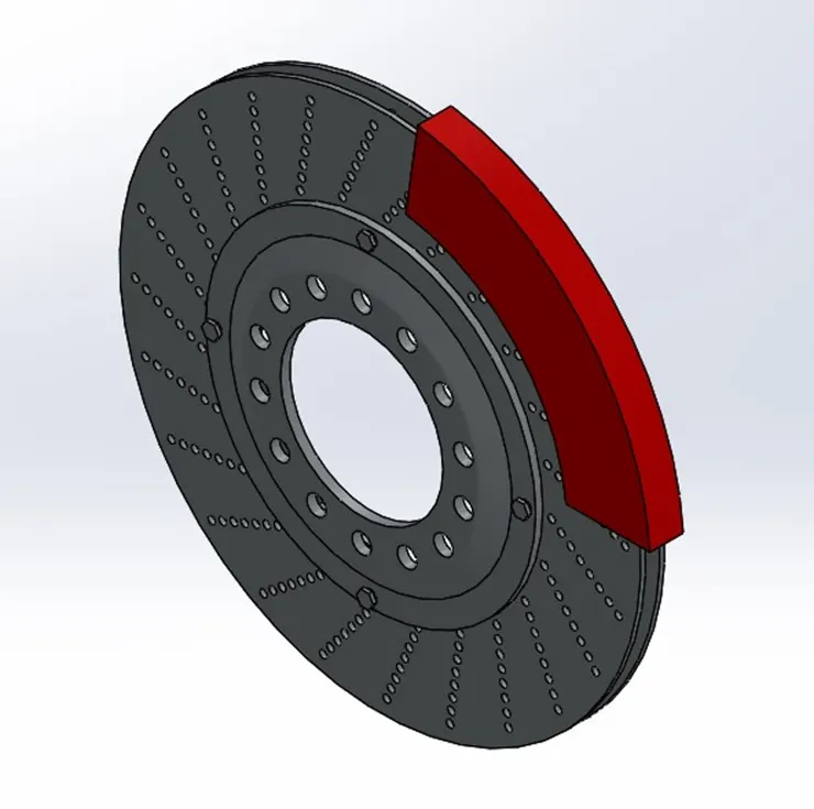
Isometric view.
- Tyre:
A tire (American English) or tyre (British English) is a ring-shaped component that surrounds a wheel’s rim to transfer a vehicle’s load from the axle through the wheel to the ground and to provide traction on the surface over which the wheel travels. Most tires, such as those for automobiles and bicycles, are pneumatically inflated structures, which also provide a flexible cushion that absorbs shock as the tie rolls over rough features on the surface.
- Creating sketches on the appropriate planes.
- Giving required dimensions to fully define the sketch.
- 3D part created using the defined sketches.
- Some linear and zig-zag patterns created on the outer face of the tyre.
- Fillets were applied to the required edges.
- Feature tools used: Revolved boss/base, Revolved cut, Reference plane, Extruded cut, Fillet and Circular pattern.
- Appearance: Dense rubber appearance given to the part.
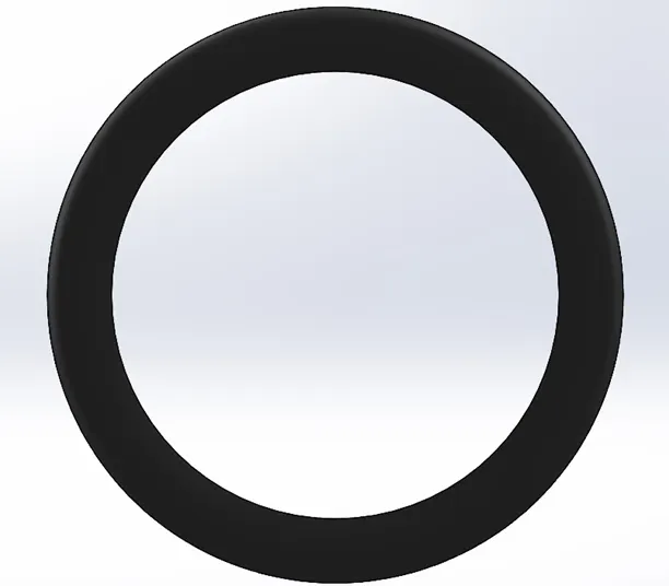
Front view.
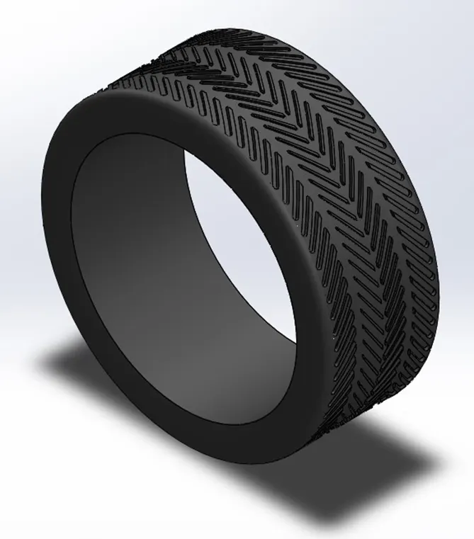
Isometric view.
- Wiper Blades:
A windscreen wiper, windshield wiper or wiper blade is a device used to remove rain, snow, ice, washer fluid, water, and/or debris from a vehicle’s front window. Almost all motor vehicles, including cars, trucks, buses, train locomotives, and watercraft with a cabin and some aircraft are equipped with one or more such wipers, which are usually a legal requirement.
- Creating sketches on the appropriate planes.
- Giving required dimensions to fully define the sketch.
- 3D parts created using these sketches.
- Fillets and chamfers are applied to the required edges of the parts.
- Mirror applied to the bodies about the mid plane to create a complete model.
- Feature tools used: Extruded boss/base, Extruded cut, Chamfer and Fillet.
- Appearance: Black colour applied to the part.
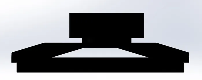
Front view.
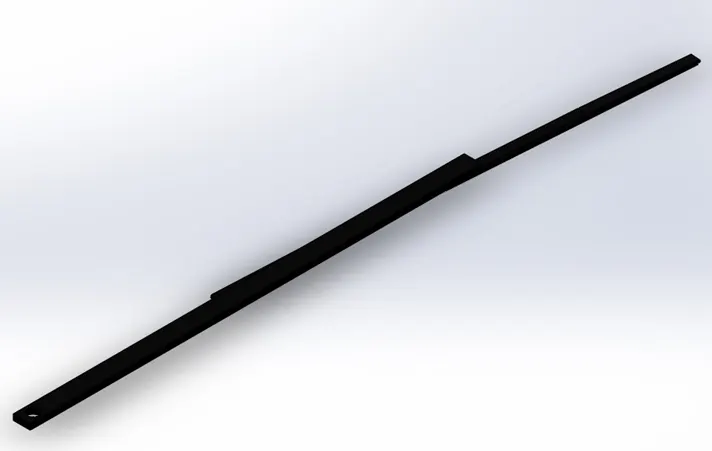
Isometric view.
Assembly:
The previously designed parts are opened to assemble them by applying some mates to appropriate planes and geometry in the assembly window. In the Lamborghini aventador model some parts are created with reference to its previous parts surfaces to simplify the assembling of parts.
- The surface body is opened in the assembly window and placed it accordingly, to assemble other parts with reference to this part.
- Then the other parts are opened one by one to the assembly window and some mates are applied to the planes and geometry of the part to the surface body.
- Once all the parts are assembled some mates applied to the assembly plane and appropriate planes of parts.
- Then some mechanical mates are given to the tyres for dynamic motions.
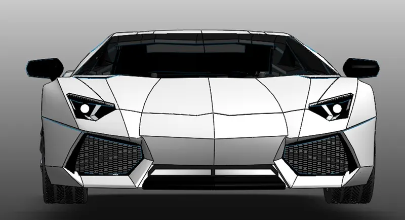
Front view.
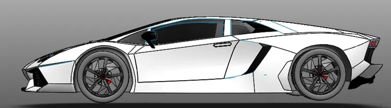
Side view.
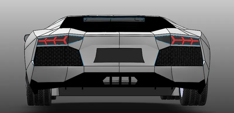
Back view.
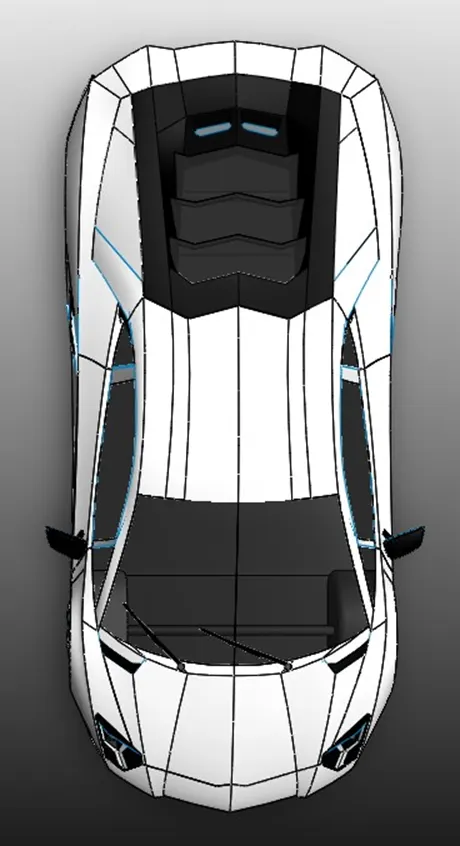
Top view.
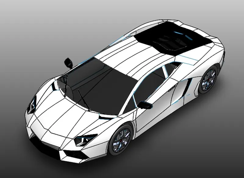
Isometric view.
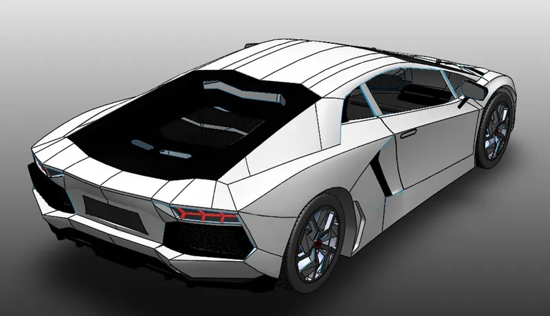
Camera view.
Correcting the flaws in the assembly:
After the parts assembly, checked for any flaws like parts over lapping. If any flaws were identified, then they were corrected by changing the geometry of parts in the part level.
Final render:
Some cameras are added in the render window with the help of photoview 360 feature in “SOLIDWORKS”, to highlight the design of Lamborghini aventador and then scenes & environments are set to the design for final render. This render showcases the realistic view of the design.
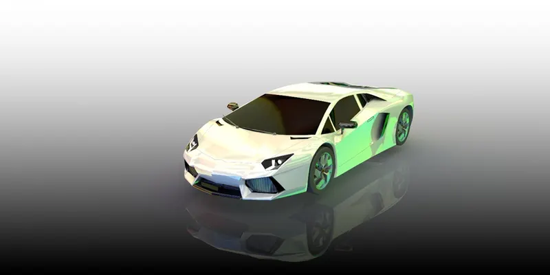
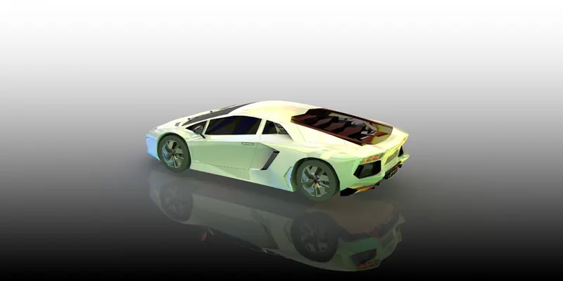
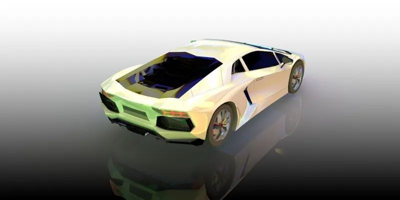
Final render of Sunseeker predator yacht shown in the above pictures.
Photo realistic rendering:
By using “SOLIDWORKS Visualize” rendering software, the appearance of the design changed and the real time ‘hdr’ scenes added as the environment to design. To make the design merged with this environment for photo realistic rendering.
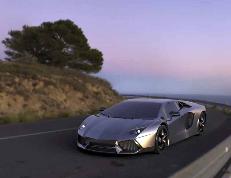
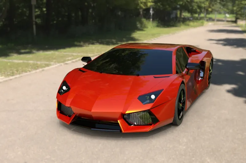
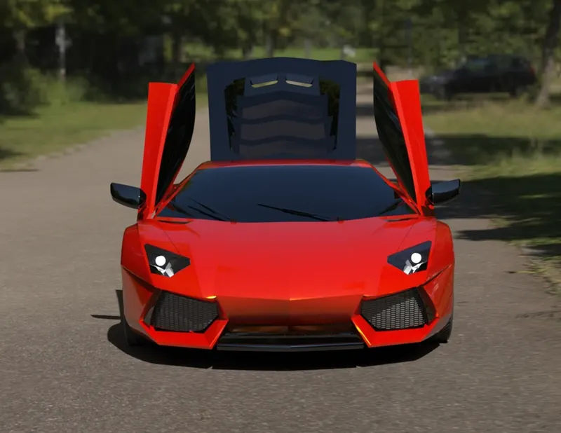
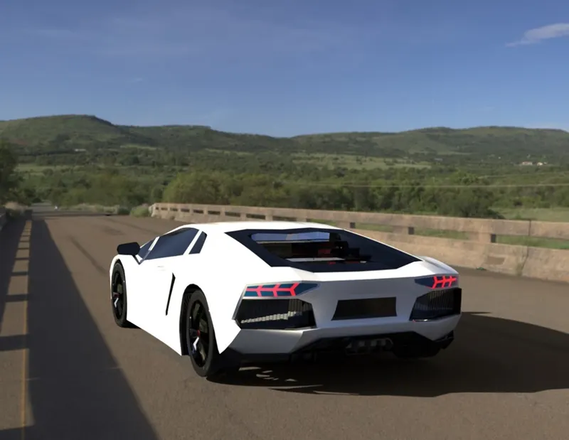
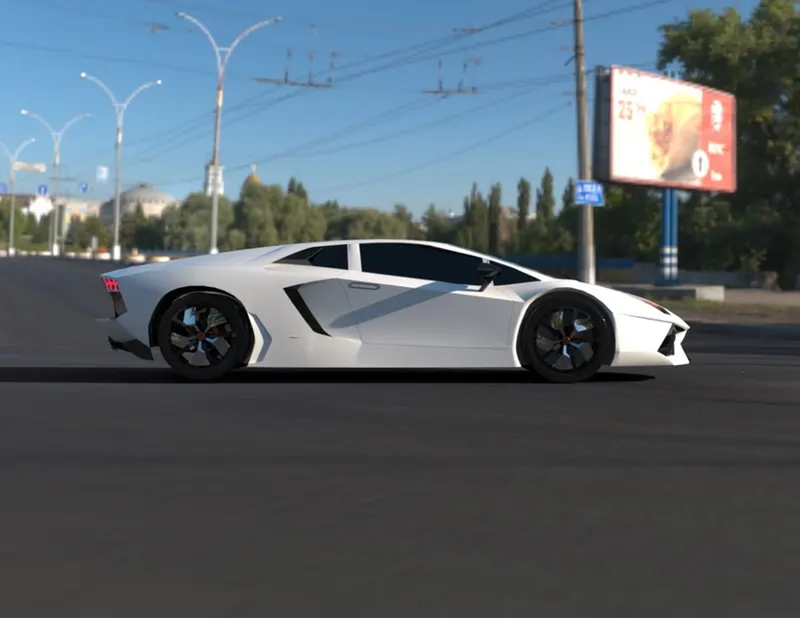
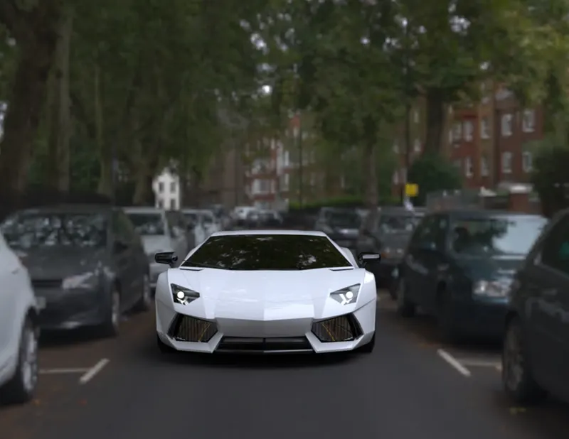
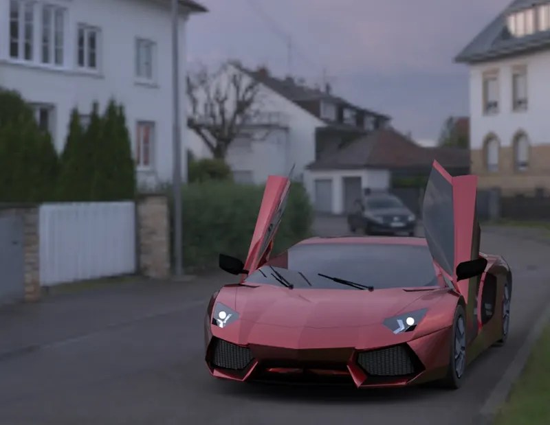
Photo realistic renders of the Lamborghini aventador in different environments in various views are shown in the above pictures.
Conclusion:
Throughout this project, two software’s were mainly used to design the parts required for assembly of a Lamborghini aventador model and to render it. And the software’s are “SOLIDWORKS & SOLIDWORKS Visualize”. In this project a design was inspired from already available aventador models and the blueprint setup of that model is set to design the parts with required dimensions and features. Then the designed parts are assembled to form a Lamborghini aventador and its flaws are corrected. After this process, cameras are added to make the model more realistic to render. Then the appropriate environment is added as a background to the model to make photo realistic renders.