Week 9 - Attachment Feature Creation - Challenge 2
TREE STRUCTURE OF THE COIN HOLDER WITH RIBS/SCREW BOSS/DOG HOUSE
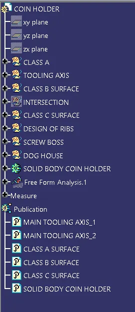
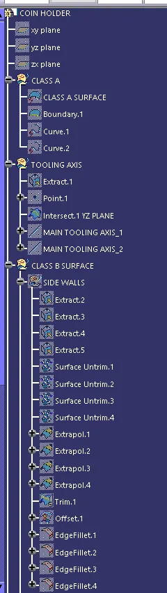
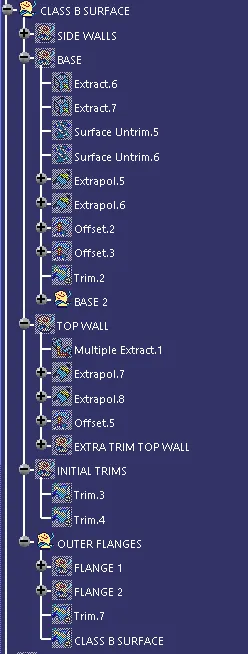
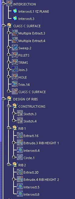
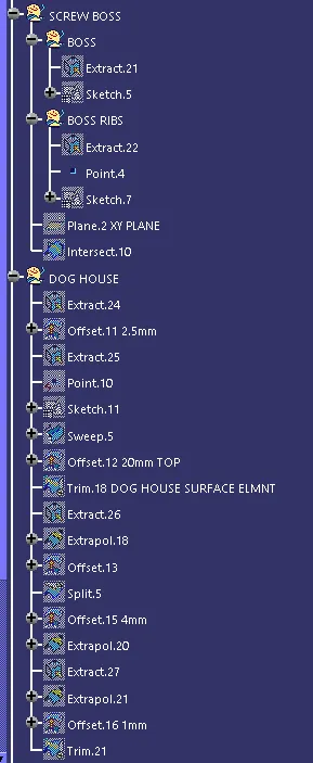
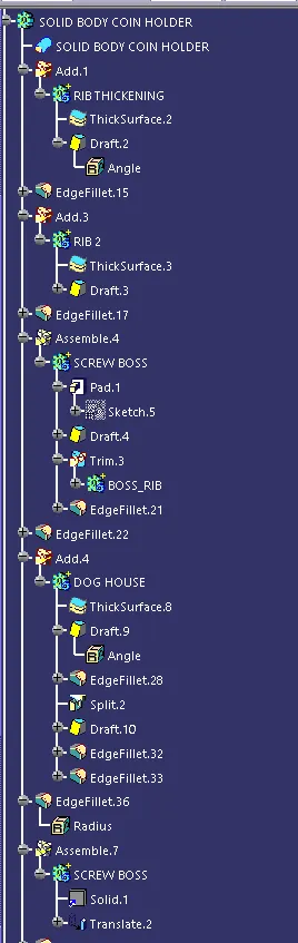
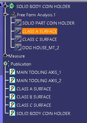
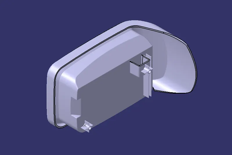
COINHOLDER VIEWS
FRONT
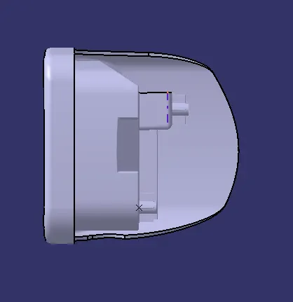
SIDE
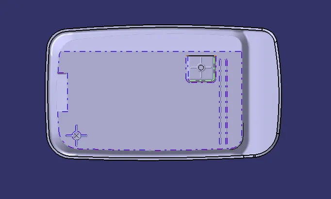
TOP
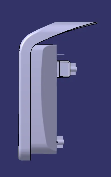
ISO
DESIGN AND DRAFT ANALYSIS REPORT OF COIN HOLDER USING CATIA V-5
OBJECTIVE: To design the Coin Holder with B-side features [Ribs, Dog House, Screw Boss] using Surface and Part Workbench and generate Drafting Analysis Report on the Class A and C using CATIA-V5.
DRAFT: When the molten plastic is completely ejected into the molded cavity and it is allowed to cool it tends to shrink to the core side of the mould and thus there deveolps a friction between the part [final output] and the mould. To overcome this drafting is required. It is required on all parts in the direction of mold movement in order to allow parts to release or eject from the mold properly.
Min draft required on final plastic component is 3mm.
DRAFTING ANALYSIS:
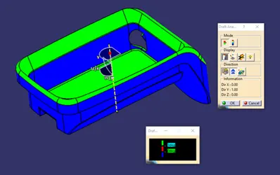
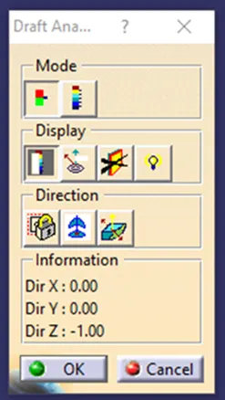
Drafting Analysis is used to generate computational analysis of the component clearing the mould cavity without any damage [by friction] between the final component. It checks whether the Main Tooling Axis is correct or not thereby analysing the draft of the component. It shows whether all faces of the component has the required draft or not using value assigned colour codes [pic 2]. It further helps us to detect corrections in the earlier stage [i.e design] thereby preventing the cost and damage to the component.
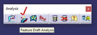
Draft Analysis Icon[01]
 [1]
[1]
Model Draft Analysis [2]
 [2]
[2]
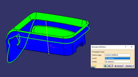
At first the component is checked for any discontinuity in the line using two techniques. Namely,
- 1. Join Definition

- 2. Boundary Tool

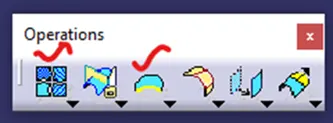
However for Coin Holder we made use of Boundary Defintion Tool available in the Operation Toolbar.
 [4]
[4]
 [5]
[5] 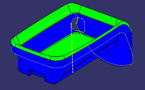 [6]
[6]
The above image ensures that the component has no discontinuity in line.
FORMULATION OF MAIN TOOLING AXIS USING BI-SECTING METHOD
TOOLING AXIS: It is an Axis which indicates the direction in which the mould/cavity opens. It can also help in designing the component according to the drafting standard of an Industry.
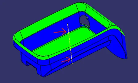 [7]
[7]
BISECTING METHOD:
Bisecting Method is used to generate main tooling axis by bisecting or dividing the two dummy tooling axis generated from intersection of planes.
It can be created in both Workbenches.
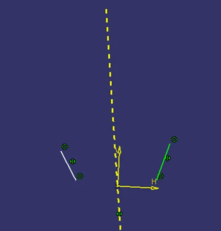 [8]
[8] 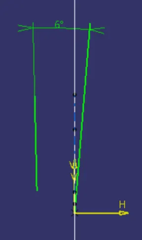 [9]
[9] 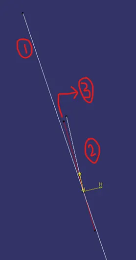 [10]
[10]
[pic 10] - 1 and 2 are Dummy tooling Axis bisected using a Line using Line Definition Tool which gives us the Main Tooling Axis [no.3 in pic].
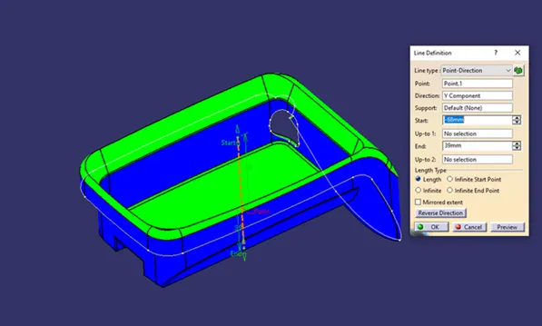
However in Coin Holder we make use of Line Definition Tool  to generate both Main Tooling Axis Normal to the surface.
 [11]
[11] 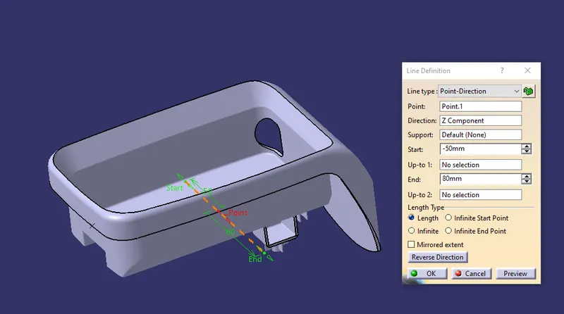 [11.1]
[pic 11] - Main Tooling Axis 1
[pic 11.1] - Main Tooling Axis 2
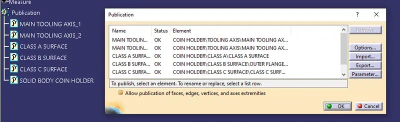
PUBLICATION
 [12]
[12]
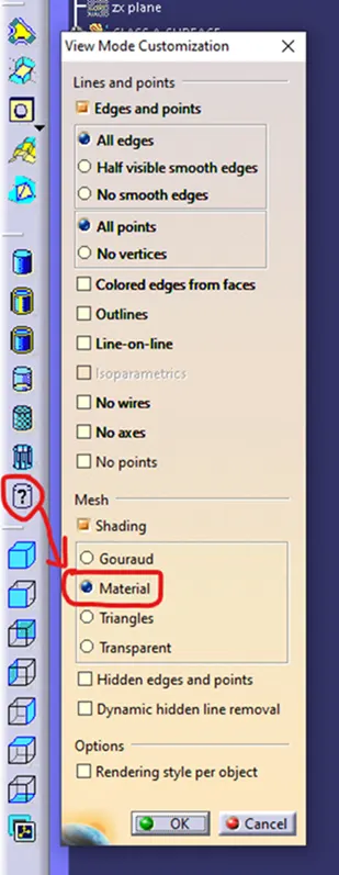
Before Publication make sure in the View Mode Customization dialogue Box, Material box is checked which is available in the Mesh Subsection.
 [13]
[13]
DRAFT ANALYSIS REPORT OF COIN HOLDER WITH B-SIDE FEATURES [RIBS, DOG HOUSE, SCREW BOSS]USING CATIA-V5
At First, Compass Tool is used to position the co-ordinate plane into the main tooling axis of the component and locked using Lock Tool
  .
.
This compass tool is available in the drafting Dialogue Box along with Lock and Analysis under Running point Tool  in the display section of the dialogue box.
A Red pointer [pic 15] appears on the component when the cursor is moved over the component under drafting analysis.
 [14]
[14] 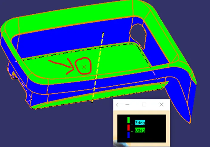 [15]
[15]
1.DRAFT ANALYSIS OF CLASS-A SURFACE
 [16]
[16] 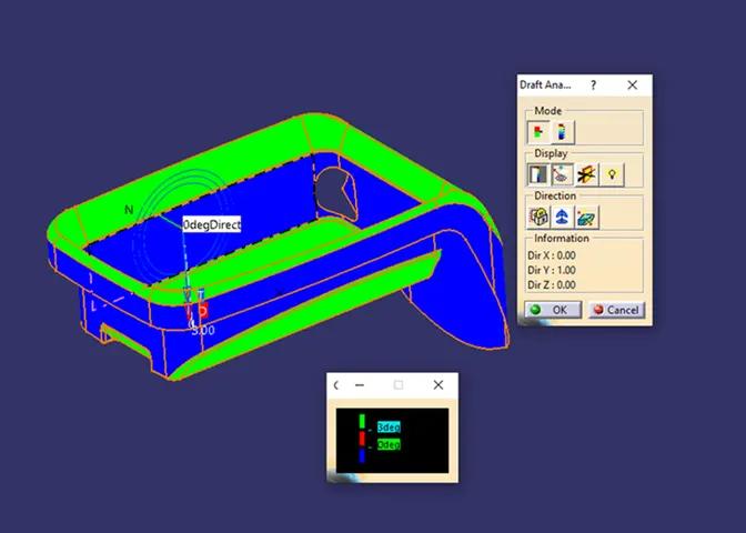 [17]
[17] 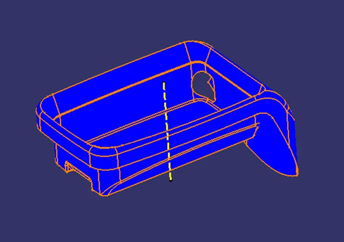 [18]
[18]
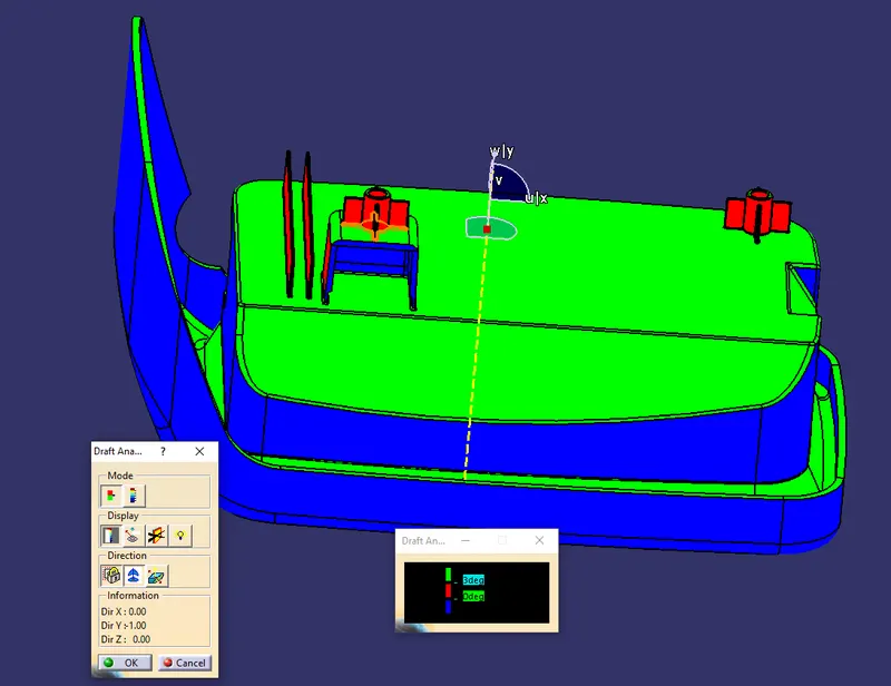
[pic 17] - shows Running point Tool to check the draft on the face.
[pic 18] - shows Inverted Tooling Axis which in turn inverts the face which is indicated with blue colour.
Observation:
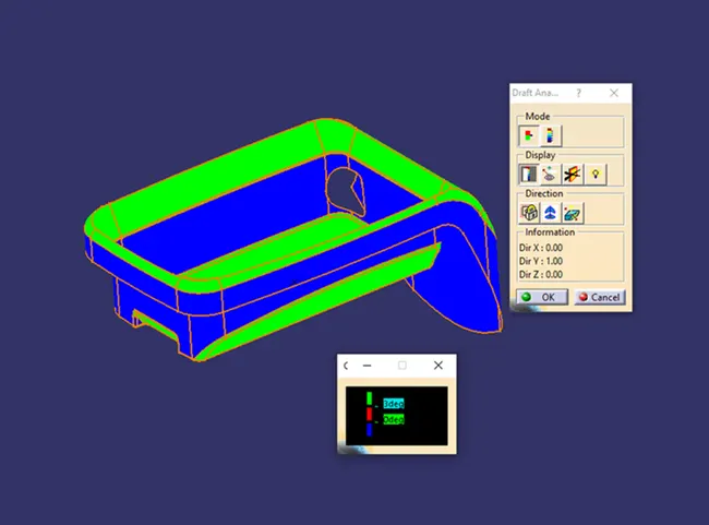
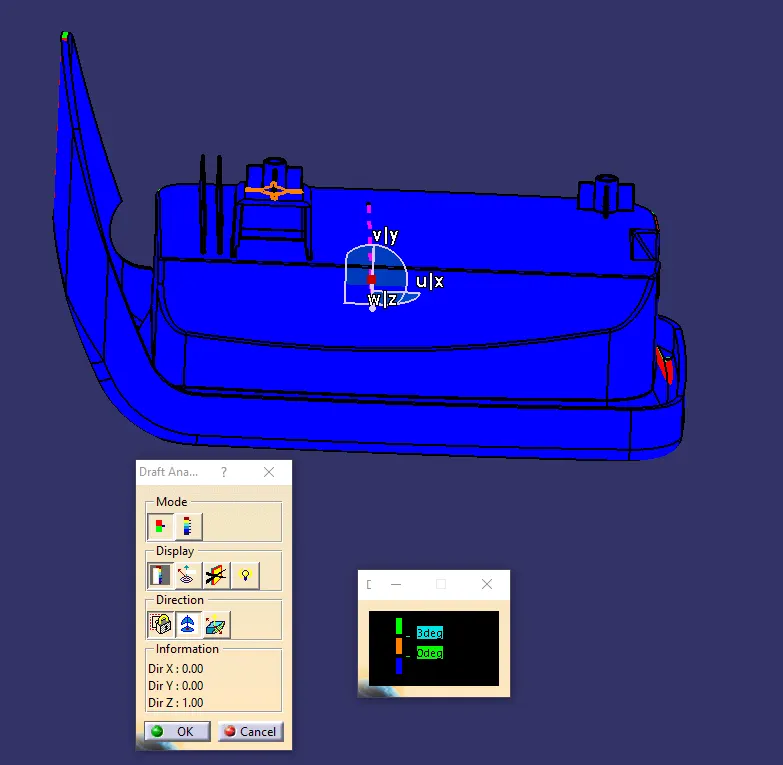
The angle between the Class A-surface [specifically Top wall and Base] and the Main tooling axis meets the requirement of Minimum drafting angle. To be specific the angle is > 3.
Another portion of the Coin Holder is Blue [pic 18] in colour indicating that the faces are inverted which inturn indicates that it could clear minimum drafting angle provided that the tooling axis is reversed or inverted.
From [Pic 18] we can understand that even after the tooling axis gets reversed it does not clears which in turn suggests to generate another tooling axis perpendicular to the hole which could clear the faces that are in blue [pic 17] and [pic 18]
The Hole in the Side Wall requires another Tooling Axis to clear minimum drafting requirement.
The Side Wall is at 0 deg indicating adjustment of tooling Axis. [pic 17]
The above draft analysis shows that the Class A- surface clears the minimum draft requirement of 3mm on one portion specifically Top wall and Base.
COLOUR CODE IDENTIFICATION
|
RED |
0 < A < 3 |
|
GREEN |
0 < A > 3 |
|
BLUE |
INVERTED |
2.DRAFT ANALYSIS OF FINAL PLASTIC COMPONENT WITH B-SIDE FEATURES
WITH MAIN TOOLING AXIS_1
` [19]
[19] 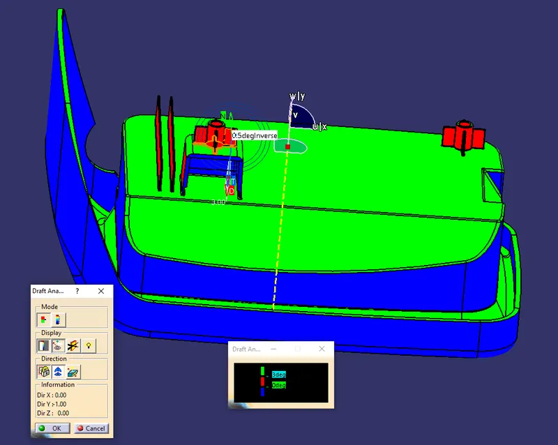 [20]
[20]
 [21]
[21] 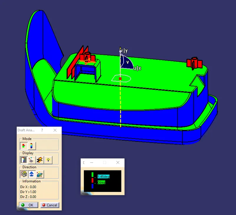 [22]
[22] 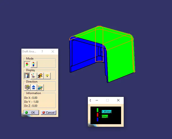 [22.1]
[pic 20] - shows Running point Tool to check the draft on the face.
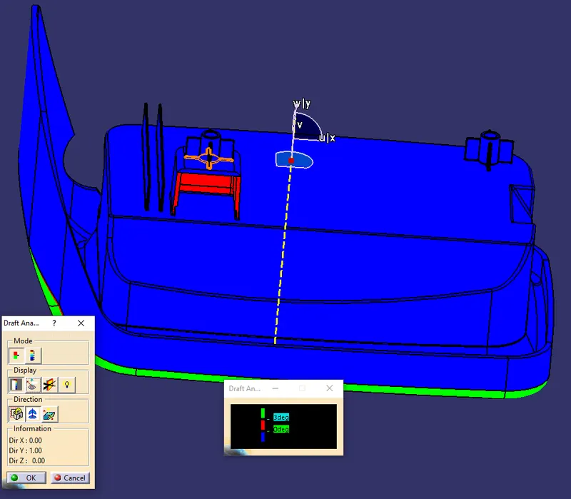
[pic 21] - shows Inverted Tooling Axis which in turn inverts the face which is indicated with blue colour.
[pic 22.1] - shows the drafting of Dog House with main Tool Axis 1
Observation:
The angle between the Class C surface and the Main tooling axis meets the requirement of Minimum drafting angle [To be specific the angle is >3] except the Ribs which have been given drafting according to the Rib Design Principles [min 0.5 deg draft per side].
While designing the Rib nominal Wall thickness 2.5mm was taken was reference. B side of the Coin Holder is Blue [pic 22] in colour indicating that the faces are inverted which inturn indicates that it could clear minimum drafting angle provided that the tooling axis is reversed or inverted.
- The Rib is shown in Red Colour indicating that it does not clear min drafting requirement of 3 deg.
- Increasing the draft angle with result in measurement <0.75mm at the top of the Rib which inturn compromises with the design principles.
- Screw Boss is shown in red colour indicating that min draft is below 3 deg indicating the need to correct the tooling axis.
- Dog House is green in colour indicating that it clears min draft required. [DH was given the inside draft of 0.5 deg and outside draft was given using the sweep tool in Main tool Axis direction.]
- The design of Dog House are done in accordance with the design guidelines for generating Dog House.
Taking all this into consideration it is suggested to correct the Tooling Axis to get desired output.
Other observations are in line with the observation made with the analysis of Class A with regard to extra Tooling Axis with respect to clearing the hole in the side wall [pic 18].
A solid part is generated in part Workbench using Closed Surface Tool .
.
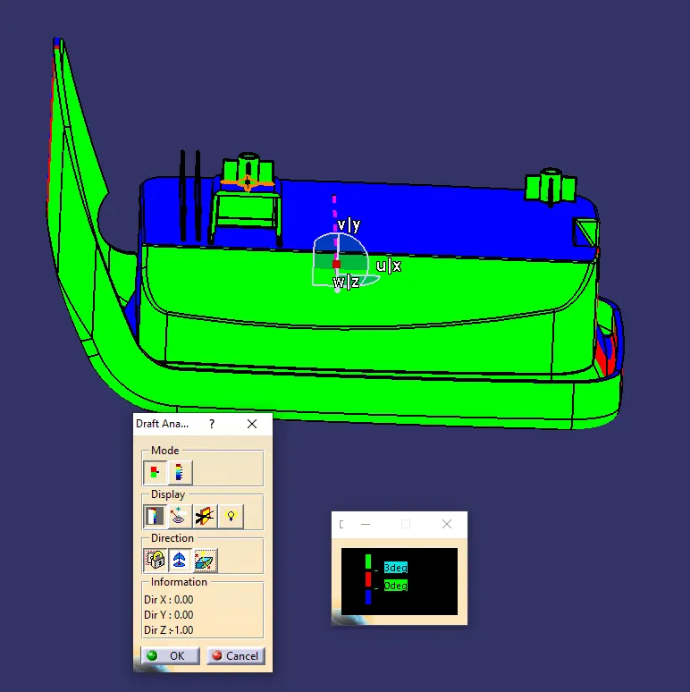
WITH MAIN TOOLING AXIS_2
 [23]
[23] 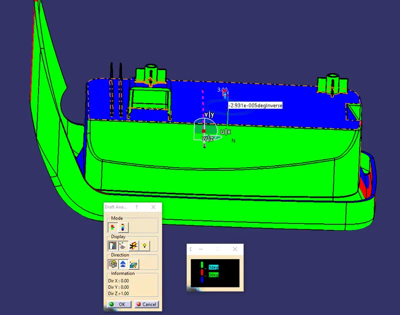 [24]
[24]
 [25]
[25] 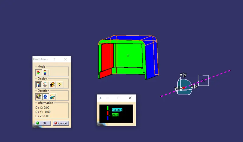 [25.1]
[pic 24] - shows Running point Tool to check the draft on the face.
[pic 25] - shows Inverted Tooling Axis which in turn inverts the face indicated with blue colour.
[pic 25.1] - shows the drafting of Dog House with main Tool Axis 2
OBSERVATION:
In this tooling direction the screw boss along with one half of coin holder component gets cleared eventhough we can see a red patches in the sides of Coin Holder.
The insides of Dog House also cleares minimum drafing requirement wich are indicates in Green colour. [pic 23]
B side of the Coin Holder is Blue [pic 25] in colour indicating that the faces are inverted which inturn indicates that it could clear minimum drafting angle provided that the tooling axis is reversed or inverted or changed.
Again, other observations are in line with the observation made with the analysis of Class A with regard to extra Tooling Axis with respect to clearing the hole in the side wall of the component. [pic 18].
Conclusion:
The Current Analysis highlights additional tooling Axis and some improvements with Designing the Ribs [w.r.t Tooling Axis] where better drafting can be achieved. Hence the component can be moved further to the Manufacturing after incorporating the necessary changes.