Week 8 - Challenge 1 - Draft Analysis on a Fan Cover
TREE STRUCTURE
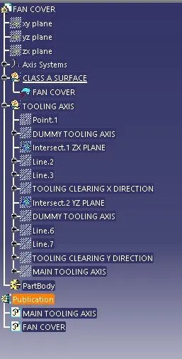
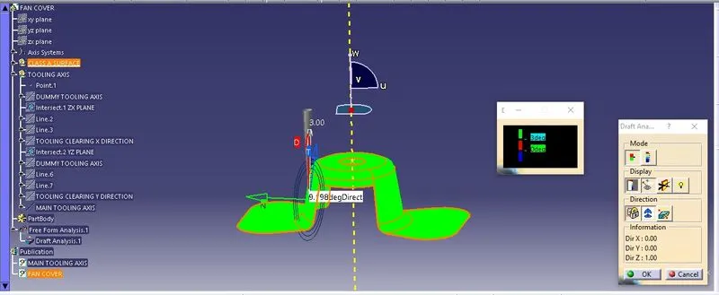
DRAFT ANALYSIS
1. WHEN DRAFT [D] = 3mm.
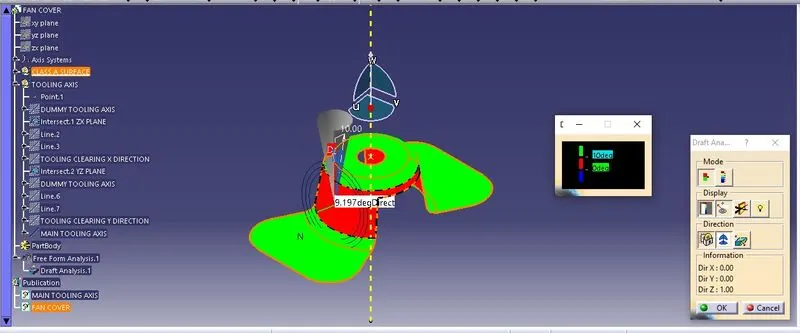
2. WHEN DRAFT [D] = 10mm.
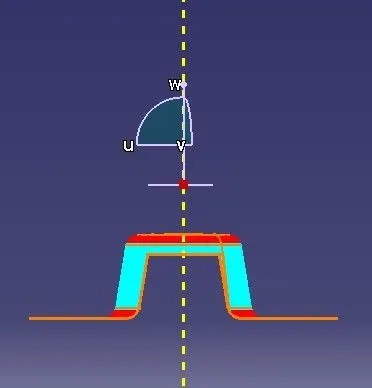
FRONT
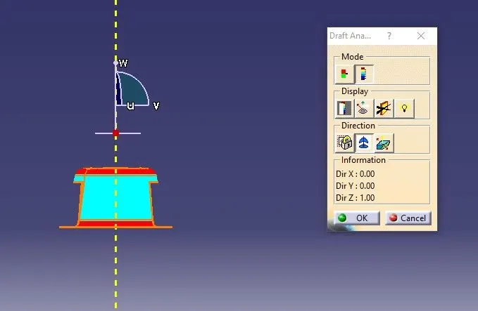
SIDE
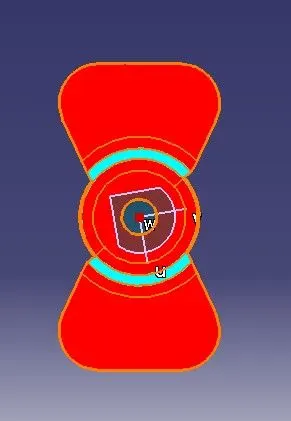
TOP
ISO
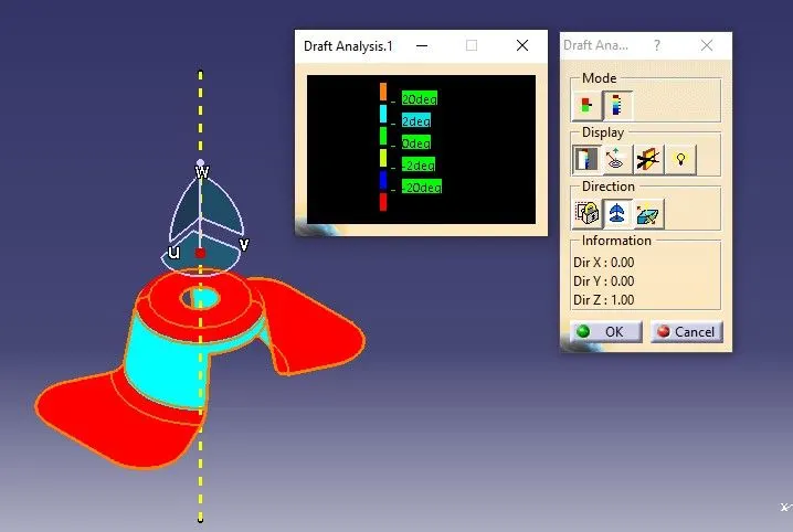
REPORT ON DRAFT ANALYSIS USING CATIA-V5:
The Aim of the Draft Analysis is to ensure the designed component/part gets removed easily from the mold specifically from tooling axis. This is done using the Feature Draft Analysis Tool . This helps to identify the deviation from the draft direction based on colour zones.
1.CONTINUITY CHECK [VISUAL]
The first and foremost step is to ensure whether the component has continuity. There is 2 ways to do it.
They are
1) Join definition
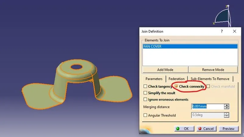
2) Boundary Tool.
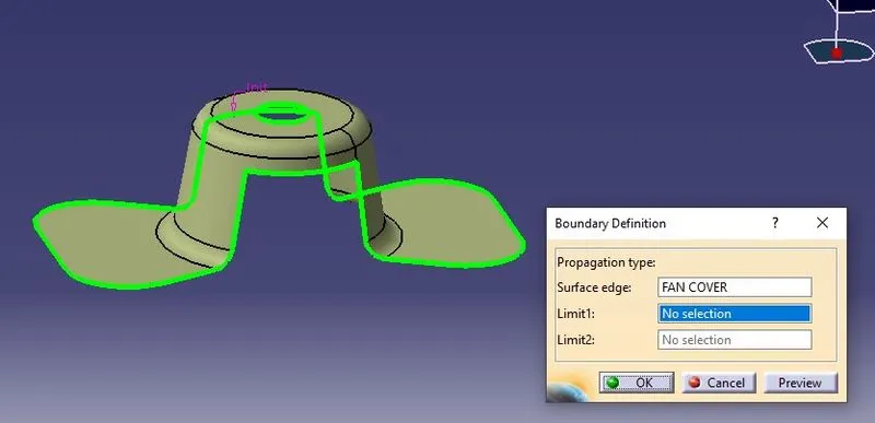
The output of those methods shows the continuous line [marked in green colour] without any breaks which ultimately conveys that the component/part can be processed for Tooling Axis formulation.
2.TOOLING AXIS
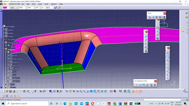
The orientation of the tool in the opening direction of the mold or cavity. It is provided for easy operability of the component.
3.TOOLING AXIS FORMULATION:
3.1 TOOLING CLEARANCE IN X-DIRECTION
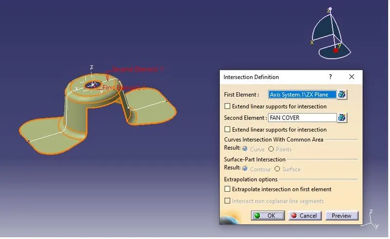
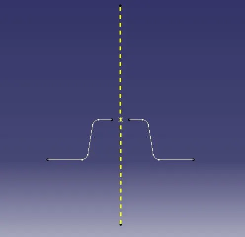
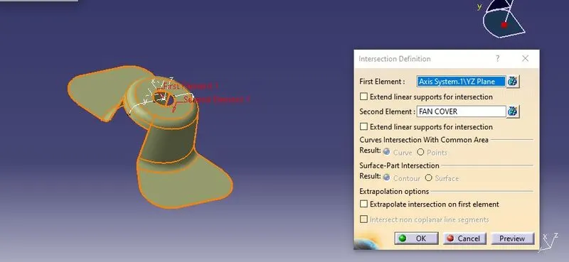
a) First step is to intersect the ZX plane with the X direction of the component to obtain the continuous line.
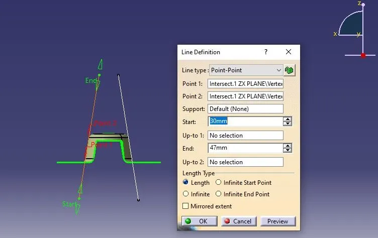
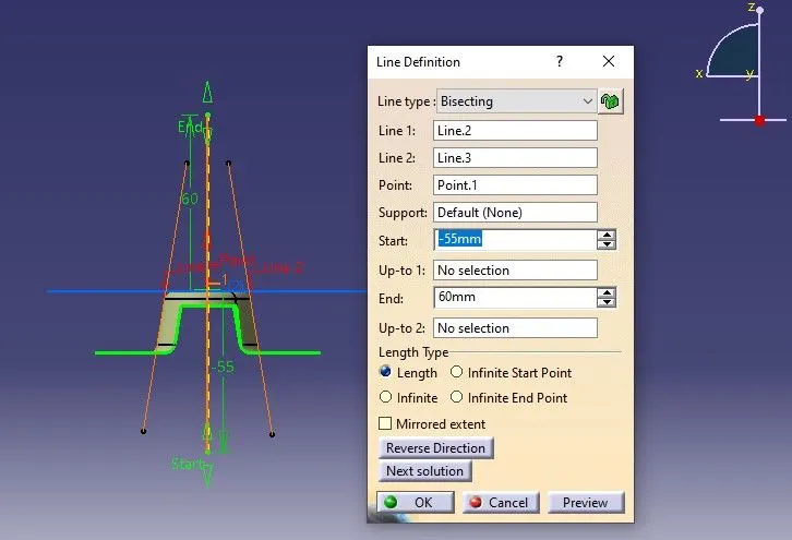
b) Next is to insert line on the intersection line on which we need to perform or identify draft angle analysis.
c) At last create a Dummy Tooling Axis in the X direction by bisecting the two lines. [Named as Dummy Tooling Axis clearing in X direction].
3.2 TOOLING CLEARANCE IN Y-DIRECTION
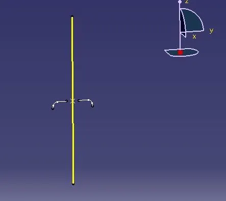
Follow the above steps given for X direction and apply the same for Y direction. The output as shown below.
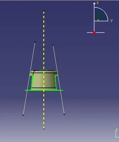
3.4 MAIN TOOLING AXIS
Now the Dummy Tooling Axis in X and Y direction are bisected to get the Main Tooling Axis.
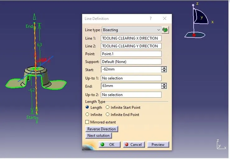
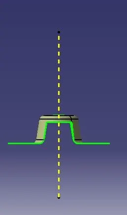
4.DRAFT ANALYSIS
Performed by the tool  .
.
- Clicking on the compass icon to place the co-ordinate plane in congurence with the component.
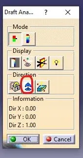
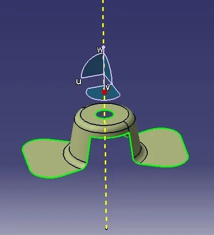
After the compass is set and locked, a red cross appears on the component when we move cursor on the component and click on the component. Colour codes indicate the draft angle as per requirement.
Green colour indicates the component is good for production.
Red colour indicates correction in the component.
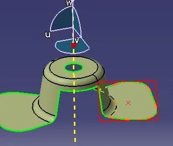
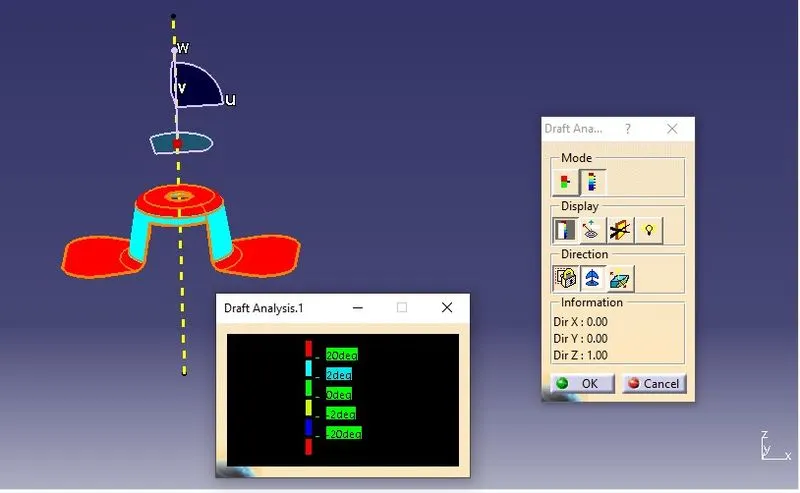
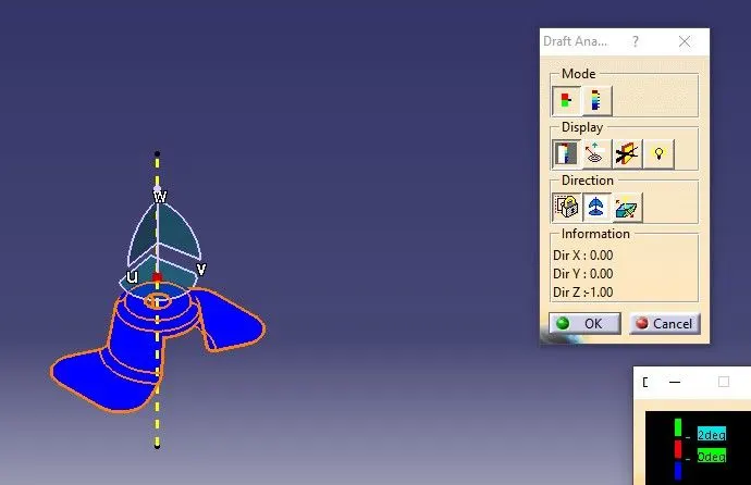
The below images shows draft angle on running point on surface.
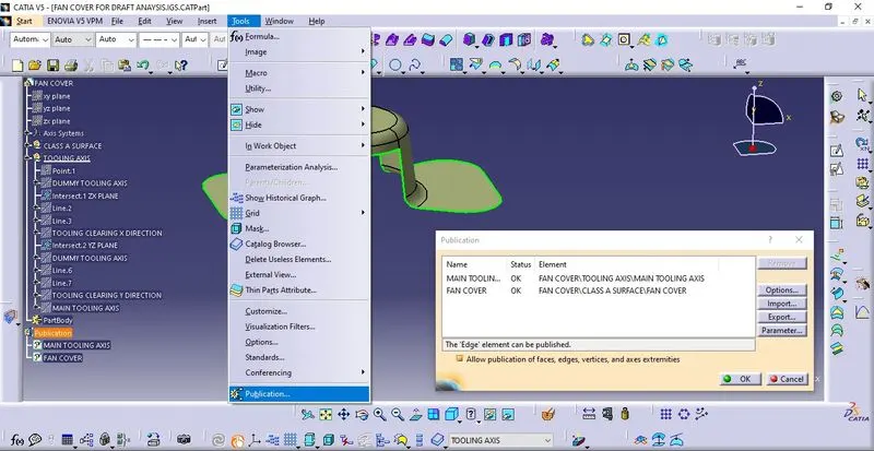
PUBLICATION
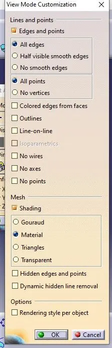
Ensure customize view parameter mode to Material before publishing the required attributes/features for highlighting purposes.
CONCLUSION:
The above Tool Axis formulation and Draft Analysis of the fan cover shows that the component is good to go for manufacturing.