Week 9 - Attachment Feature Creation - Challenge 2
REPORT :-
1) OBJECTIVE :- To create Screw-bosses and Doghouse on the coin holder and do the Draft Analysis of the final component.
2) what is :-
- DRAFT :- Draft is providing angles or tapers on product features such as walls, ribs, posts, and bosses that lie parallel to the direction of release from the mold. This eases part ejection.
- DRAFT ANALYSIS :- This identifies the zones ( using color codes ) and highlights the areas which deviate from the specified values along a defined draft direction. 3 Degree id nominal Draft.
- TOOLING AXIS :- This the Axis along which the mold will eject.
3) DRAFT USES :- Draft is required on all parts in the direction of mold movement ( i.e Tooling Axis ) in order to allow parts to release or eject from the mold properly. Draft is the angle in which the part is tapered to allow it to release properly. As the part cools, it tends to want to shrink to the core side of the mold.
4) PROCEDURE :-
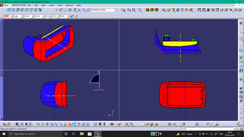
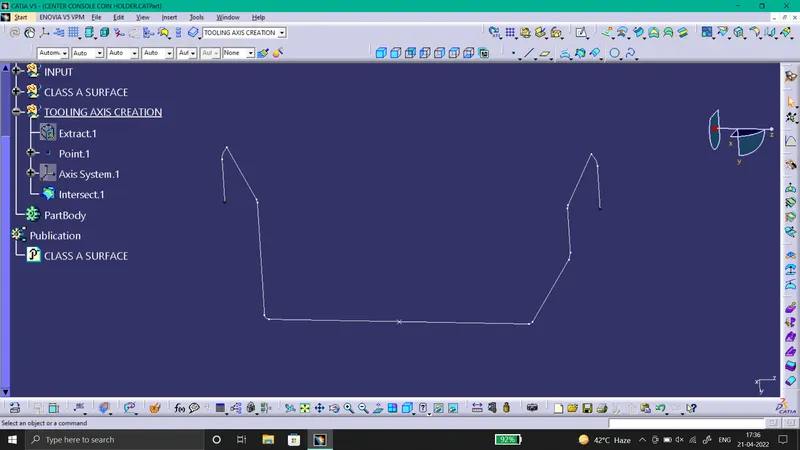
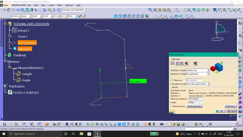
For Draft Analysis, 1st we have to create a Tooling Axis. So, see all sides of the component and observe all the planes, watch for side core and decise the direction of Tooling axis. To draw Tooling axis we will create a point on the base surface. Then insert a Axis System, we will intersect the Y-Z plane with the component. By observing the intersection, we come to know that there are no draft sides, the sidea are at 0degrees as shown in images below. And as it is a Bin Structure we will create the Axis on the point create on the base surface. Hence, we will get our required Tooling Axis.
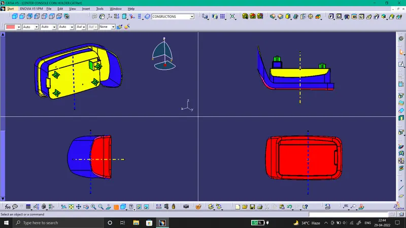
Then For Draft Analysis on Class A surface, click on the Feature Draft Analysis command in the part workbench. Insert the compass on the Tooling Axis and lock it their, As shown in Image. Then click on the surface, we will get the required Draft Analysis with color. For the Draft Analysis of the close component, perform the similar steps.
Then for Draft Analysis of the Dog House we will need to Tooling Axis, as it have a Side core. Then we will create a line on the same point we use for the pervious tooling axis in z-direction. Then we will do the draft analysis of the Doghouse for both axis.
And last we will do Draft Analysis of the final component with screw boss and Doghouse by similar steps as we have the Tooling Axis.
5) CONCLUSION :-
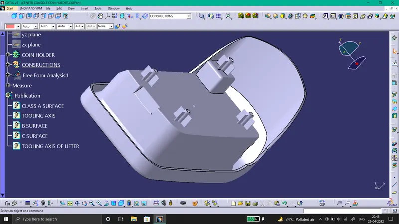
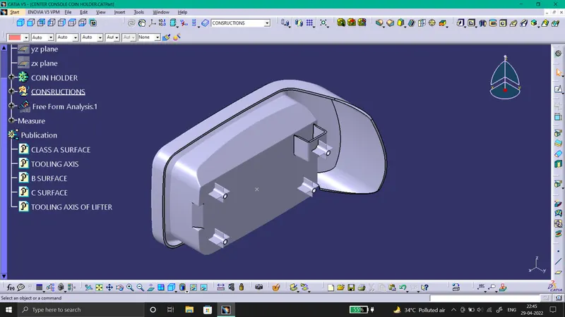
- Screw-Boss is created with proper draft angle (0.5 degees).
- Dog House is also created with proper draft angle inside and outside (Outside 1.5 and inside 0.5 degrees) . ( As shown in Images.)
- The Components are made with proper draft and Tooling Axis.
6) Below are the Images:-
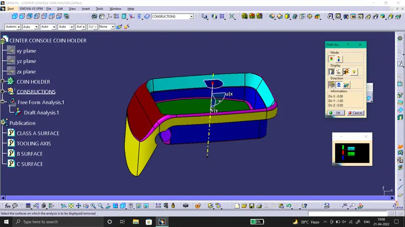
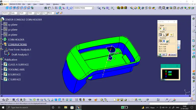
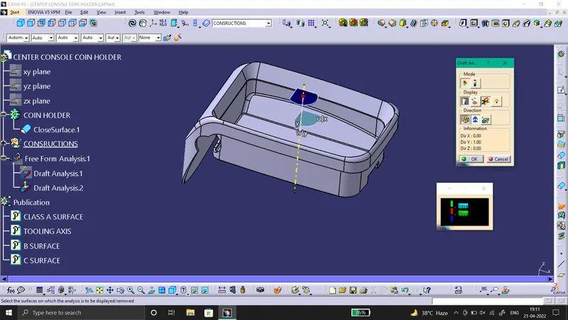
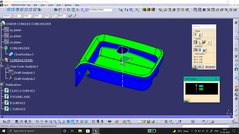
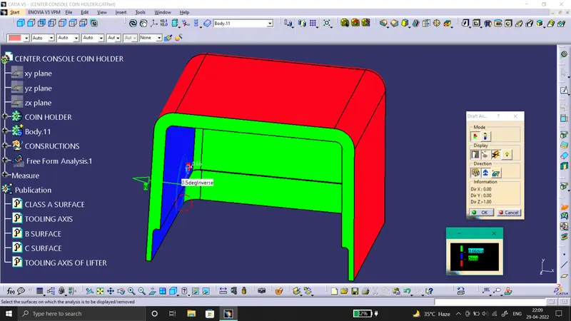
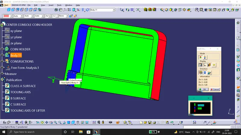
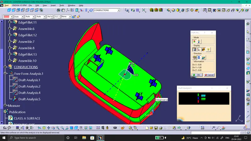
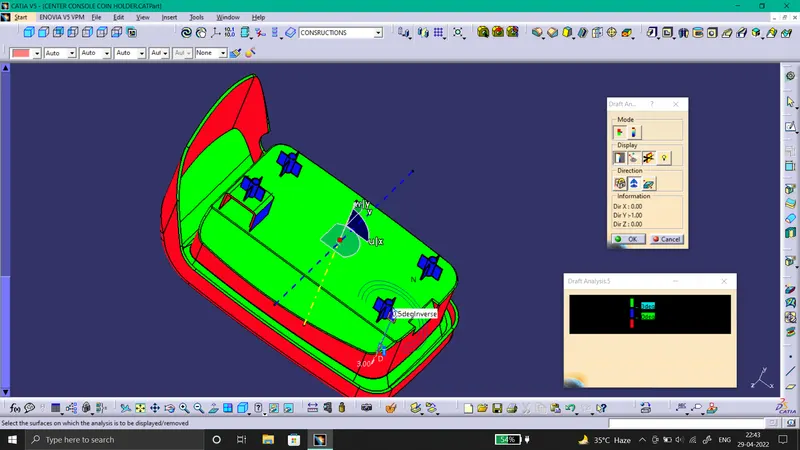
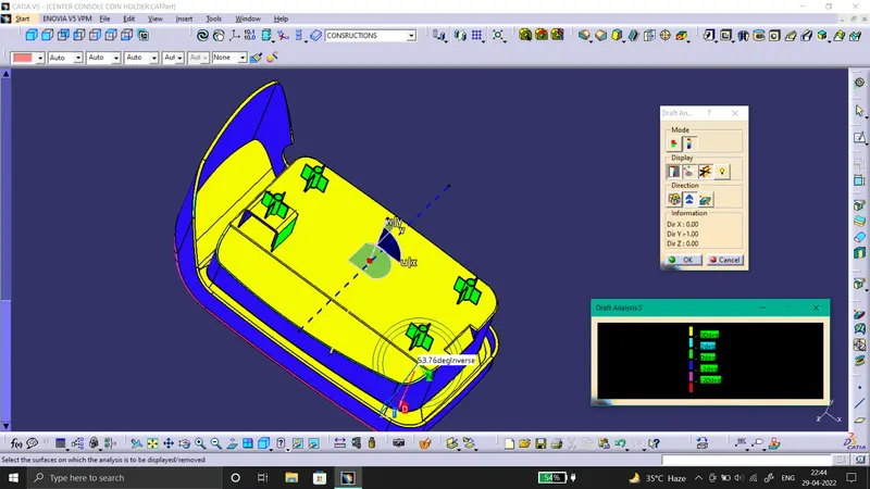
- SS of the completed design in various orientations (Isometric, Front, Side, and Top View).