Week 9 - Attachment Feature Creation - Challenge 2
REPORT- ATTACHMENT FEATURE CREATION: SCREW BOSS AND DOG HOUSE
INTRODUCTION-
The screw boss and Dog house are secondary attachments feature used to connect or assemble the plastic part.Generally screw boss and dog house are assembled with each other on Class B surface.These are increases the supportive strength to plastic part.
DESIGN PROCEDURE-
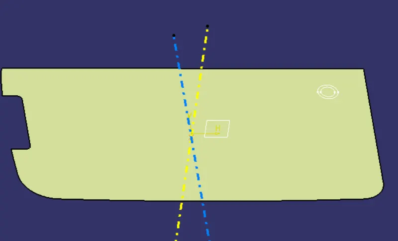
- Creation of Tooling axis both like main tooling axis & side core tooling axis
- Design of attachments like SCREW BOSS & DOG HOUSE
- Generate Draft analysis report on screw boss and dog house
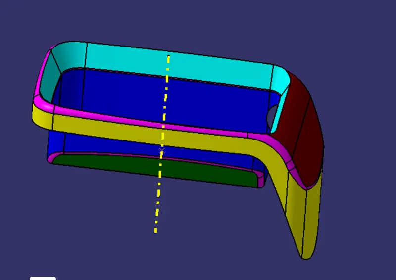
CLASS A-SURFACE-
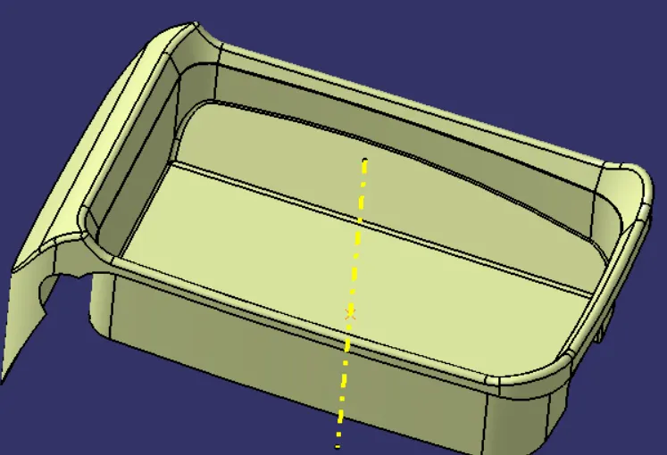
CLASS B-SURFACE-
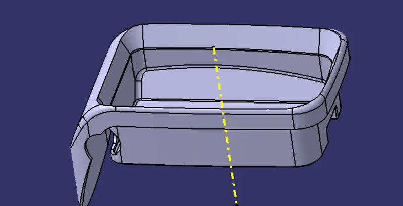
SOLID BODY-
SCREW BOSS-AS the name indicates it is used for fastners purpose on plastic parts.Screw boss created along with Class B-surface and A-surface in mould tool.The direct attachment of screw on class A-surface asthetically not good so to fastning screw ,seperate bosses are designed on Class B-surface.Generally screw boss have inside hollow portion with thread feature to lock the screw. To proper disengagement of screw draft provided.
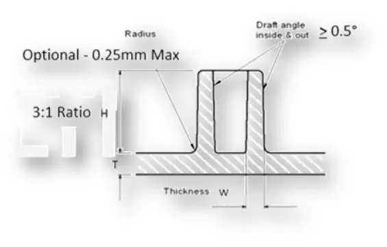
design standards for screw bosss-
- wall thickness : IT Should be 40% of wall thickness of components.
- Height ration: It should follow ration betweem height of rib and diameter and it is 3:1 or 2:1
- Draft: minimum 5 degree on each wall
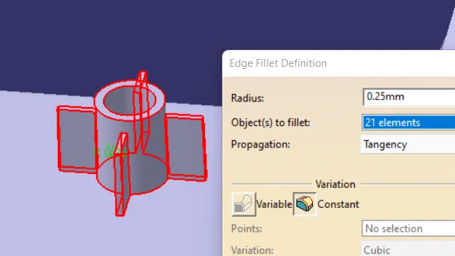
- Fillet radius: The minimum radius of 0.25 mm are providing.
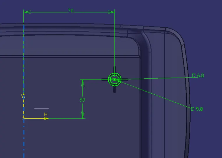
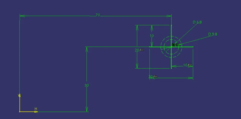
1.base creation- Extract the supportive base surface from class A-surface and sketch the screw dia. with diameter 6.8 mm.
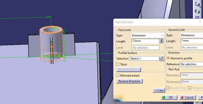
2.Boss extrude-
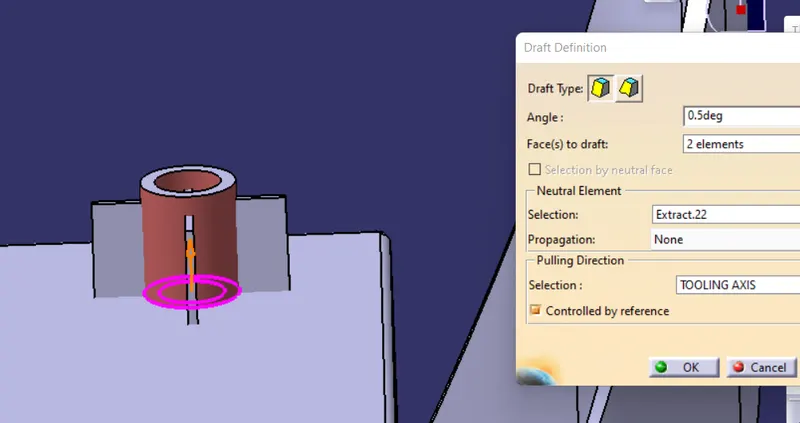
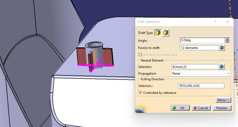
4.Draft :inside and ouside of 0.5 degree
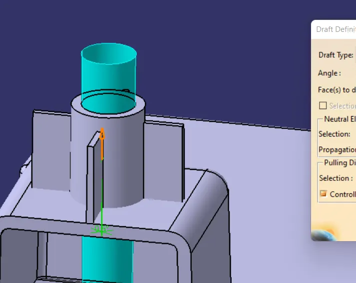
3.suportive rib structure-
4.Fillet radius of 0.25mm minimum.
DOG HOUSE- Dog house is an engineering feature that used in plastic parts design for provide supportive strenght as like screw boss.Mainly dog house ans screw boss are used to avoid the sinc mark and other plastic defect on Class A-surface.
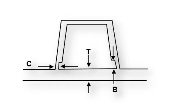
STANDARD RELATION -
- At intersection of main part and dog house base wall ,the thickness should be 40% or less than the main part wall thickness.
- The height (B) should be between 3 to 6mm.
- The draft at outside wall should be 1.5 degree.
The design procedure are as follows-
- Extract the base surface for sketch purpose from Class A-surface of components.
- Make sketch of rectangle with one side should be open and Swept with draft tooling direction by using draft angle 1.5 degree inward.
- Apply the thicken surface with specific thickness value as per design rule.
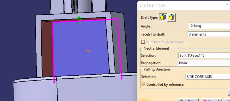
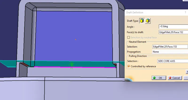
- To easy opening from side core ,provide the inside draft angle of 0.5 degree.
- To avoid the sink mark at intersection of wall and dog house,make slot cut of 3 to 6 mm in thick.
- The sink saver thickness should be 40% of wall thickness.
- Make inside draft of 0.5 degree for sink saver slot.
- Split the sink saver slot with dog house part and apply the proper fillet value.
- Mount the Screw boss on dog house.
Dog house creation as per design rule are as-
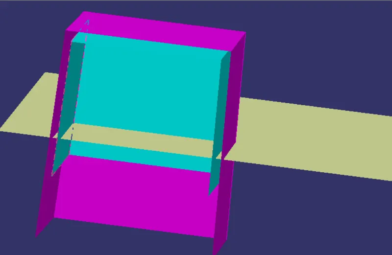
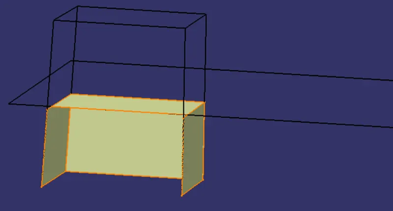
1.Extracting base surface and swept sketch with 1.5 degree draft,trim it with offset surface
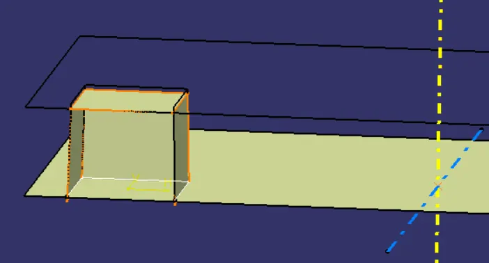
2.Apply the thickness of 2 mm
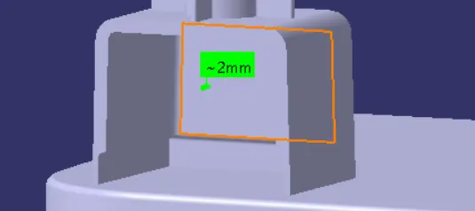
3.Provide the inside draft of 0.5 degree.make sure that material should be cut down.
4.design of sink saver-
- Offset the base surface with 4 mm
- Extract the inside wall of doghouse and offset it as per design rule and it should be 40% of 2.5 mm wall thickness i.e.1 mm
- Etrapolate the ofset surface eith suitable value.
- Apply the trim command to get shape of sink mark.
- Use the split to cut the inside portion of dog house.
MOUNTING OF SCREW BOSS ON DOG HOUSE-
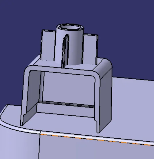
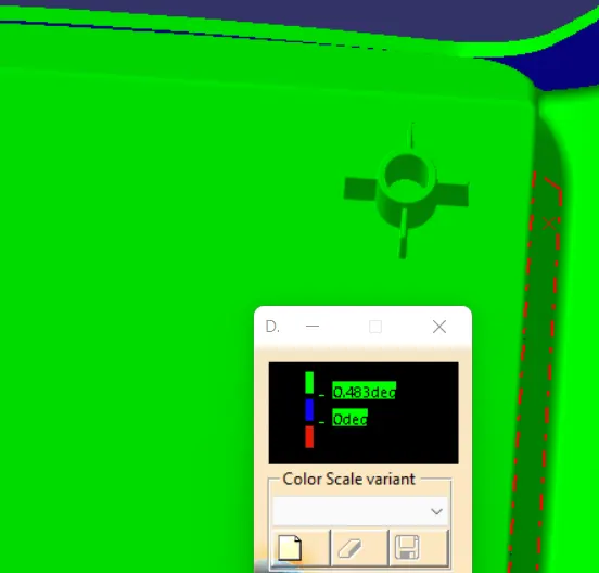
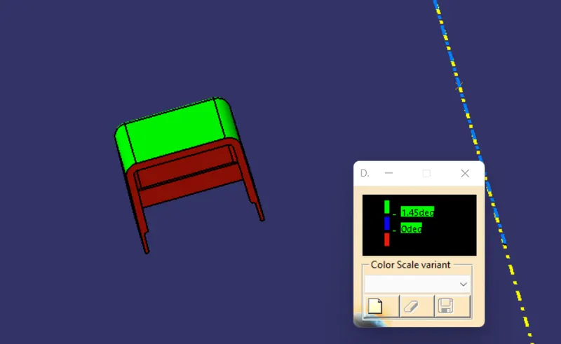
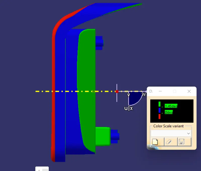
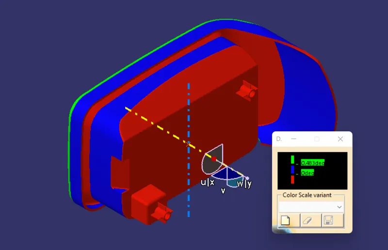
DRAFT ANALYSIS OF SCREW BOSS AND DOG HOUSE-
**Procedure to create Draft Analysis-
1.Open the part file in Catia workbench.
2.Apply the material for part.For that go to view feature>Render style>Customize view parameter.
3.For draft analysis we have to select Insert>Analysis>Feature draft Analysis.Then there will be opening the Draft analysis dialogue box with showing icons like mode, display and direction.
4.Move the compass towards the tooling axis and coinside it with tooling axis.If you want to fix the compass then click on lock icon .
To start the analysis-
1.Select the surface of Part that we want to analysis.
2. click on draft analysis icon .
3.MODE OPTION-
In dialoue box showing mode option with quick & full analysis mode.In that mode feature we can understand the different angle range value in colour format which indicate part is in correct drafft mode or not.The default mode is the quick mode. It simplifies the analysis in that it displays only three color ranges.
* Doble click on colour range which display in dialogue box and we can change the colour range.
*Also by double click on the angle value ,we can modify it.
*The colour mode and respective Draft angle value is set in mode dialogue box.
- When the Draft angle value of the surface is equal or smaller than graduated (fixed in dialogue box) value,the colour will be applied as per graduated value to the surface.
- When the Draft angle value of the surface is greater than greatest value of graduated,the colour of graduated value is applied.
4.DISPLAY OPTION-
- colour scale-this dialog box only appears in edition mode.Means we have to activate Full mode or Quick mode analysis.
- Angle Pointer-activate the pointer and move it over the surface which showing various draft value at different locations.
Arrows are displayed under the pointer, identifying the normal to the surface at the pointer location (green arrow), the draft direction (red arrow), and the tangent (blue arrow). As you move the pointer over the surface, the display is dynamically updated. Furthermore, circles are displayed indicating the plane tangent to the surface at this point.
3.No highlighted & Representation icon-This feature gives option like on/ off the highligh portion of part.As it enable ,it will show all edges in colour (highlight) format.
4.LIGHT EFFECT-This feature helps to understand the visualisation effect of part under light effect.This light effect will affect the visualiser's eye.
5.Inverse direction- It allows to change the direction of draft angle of selected part.As the we click on reverse direction then there is changing gaduated colour effect ( in negative).It shows the BLUE colour.
5. DIRECTION -
- LOCKED DIRECTION- In that we can lock or unlock the draft angle direction,a plane,a Face which is used in current analysis.
- COMPASS- It is used to define the new or current draft direction.To set the compass direction on Tooling Axis,we have to move or pull the compass origin and coinside with tooling axis.
6.Once we have finished the analysing the surface by applying propper elements CLICK on OK icon in DRAFT ANALYSIS DIALOGUE BOX.The analysis is added to tree chart of part.
IN this way we can genrate the report for Draft Analysis for a given part by using Feature Draft Analysis.
1.SCREW BOSS-
2.DOG HOUSE-
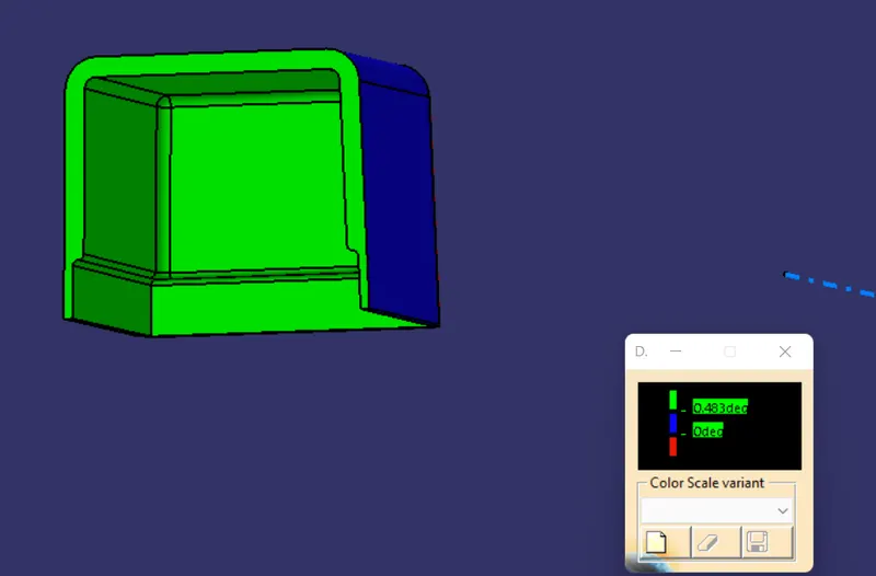
1.FRONT VIEW-
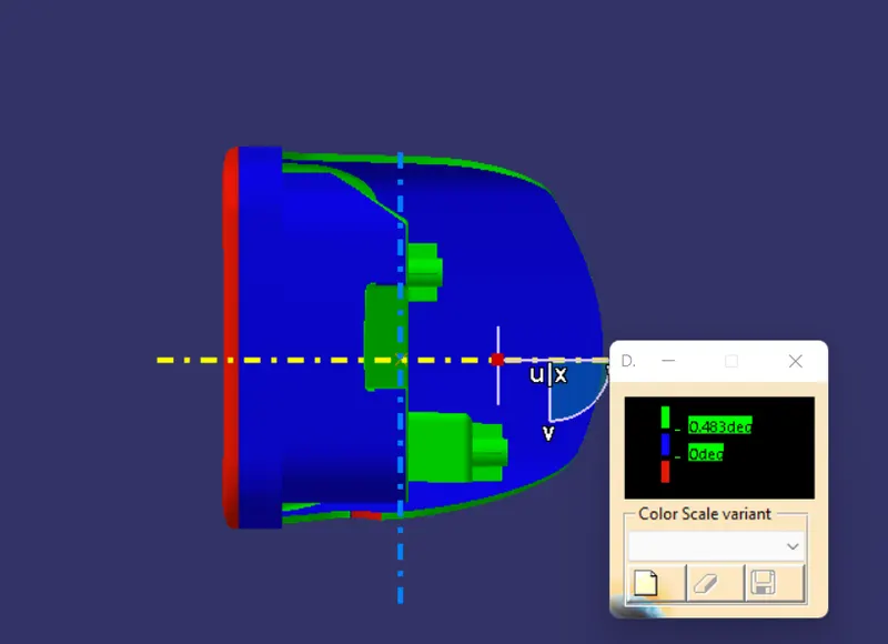
2.SIDE VIEW-
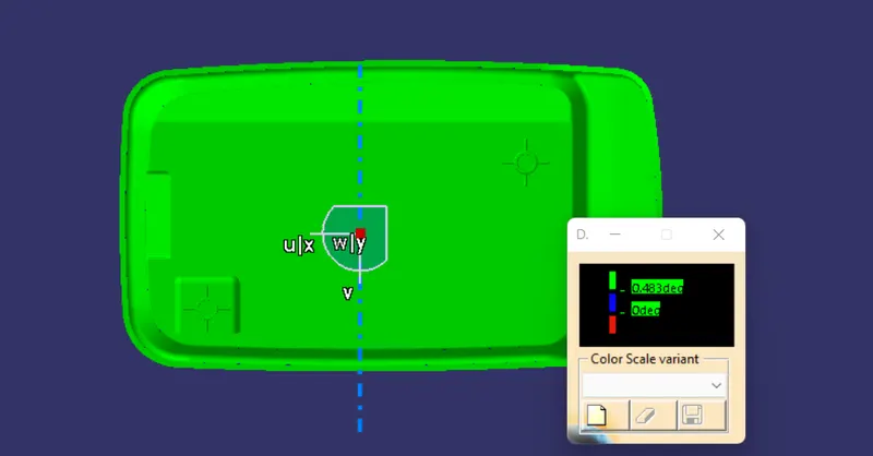
3.TOP VIEW
4.ISO. VIEW
CONCLUSION-
The plastic components are assembled by using attachment feature like RIB,SCREW BOSS, DOG HOUSE.By using them wr can assemble the part as well we can provide strength to assembly.Basically these feature are generated under Class B-surface due to it's asthetic look.So customer can see only Class A-surfacewhich is good in asthetic look.The attachment features are designed with standard rule to overcomes eith plastic deffect.
- Learn to importance of attachment features
- Learn to Standard design procedure to generate attachment feature like rib ,screw boss and dog house.
- Learn to various plastic defect occures in plastic component like sink mark ,flash, short shot,Air trap,burn mark,flow line.