Week 9 - Attachment Feature Creation - Challenge 2
SCREW BOSS & DOG HOUSE DESIGN OF COIN HOLDER
AIM- To create the screw boss and dog house for center console of coin holder considering every design rule in industry.
THEORY OF SCREW BOSS AND DOG HOUSE
SCREW BOSS- The boss is one of the basic design elements of a plastics moulding. Bosses are usually cylindrical because that is the easiest form to machine in the mould and it is also the strongest shape to have in the molded part.
Boss features are commonly found in injection molding designs. They are used to aid in the assembly of molded parts by providing a channel for a screw a thick enough wall so that the screw can engage with the plastic without splitting the post.
The boss is used whenever we need a mounting point, a location point, a reinforcement around a hole, or a spacer. Their primary use is to strengthen holes or slots in the surface of your part. Plastics designers love thin walls, but thin and strong are opposites ends of the trade-off spectrum.
An ideal boss designed with rib rules. But in real life most bosses break some rib design rules by necessity. That why the support ribs can be designed to normal rib rules so that sink marks and stress points are avoided.
DESIGN RULES FOR SCREW BOSS
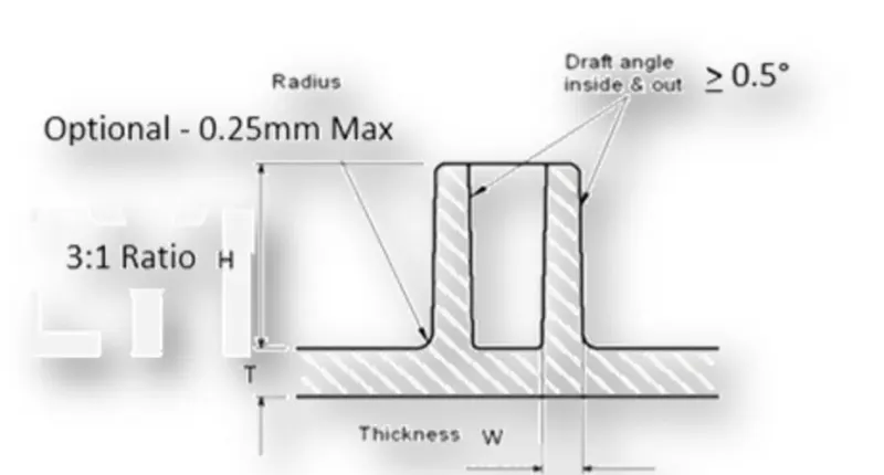
RULES: -
- Draft 5degree on wall of boss.
- Thickness 40% of the nominal wall at the base.
- Height to diameter ratio 3.1
- Radii 25mm maximum radii.
- Boss gusset (structure giving strength to the screw boss) must meet rib guidelines.
- Avoid merging the screw boss into wide wall.
DOG HOUSE- Dog house is an engineering feature used in plastic trim design. Dog houses are used as supporting feature. Sometimes other engineering features like snaps; locators etc. are mounded on them to increase their strength. These are hollow inside and so they are also a shell structure.
Primary function of dog house is to avoid sink marks. But it also helps in other thing like if the mating part is to be at a greater distance than we can not make the height of the screw boss greater height, thus we make dog house and mount screw boss on it. Hence it helps in solving the problem of screw boss and also it helps to perpendicular screw boss.
DESIGN RULES FOR DOG HOUSE-
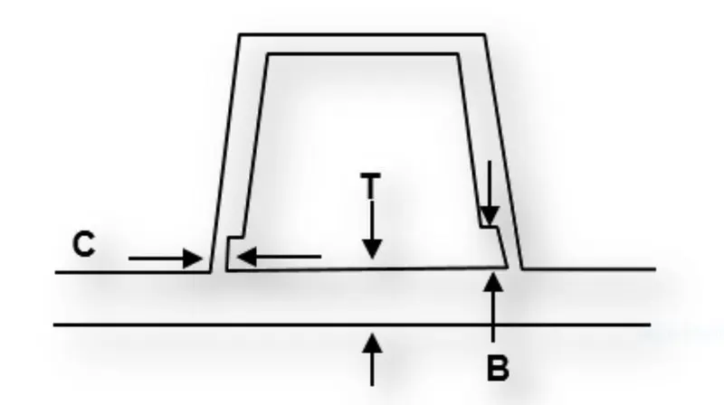
RULES-
- ‘C’ is where the dog house contacts the back side of the surface.
- Dog house wall thickness at the intersection of part walls should be 40% or less than the main wall stock.
- Height of ‘B’ should be between 0-6.0
TOOLING AXIS: - In this model we have created two tooling axis one for clearing the outside faces of the dog house other for clearing the inside faces of dog house. These two axes are two different direction one is Z and another is Y.
- Make an axis system and intersect the model to be analyzed required plane.
- Once we get the intersection line, we will make lines on the lines which represent those surfaces.
- Then intersect those lines to get to one line.
- Then we will do the similar procedure for the other two parallel faces which are perpendicular to the earlier faces so that we get two lines which intersect each other.
- Once we get two lines which are tooling axis for two different pair of faces, we will make a line which bisects these two lines. This is main tooling axis.
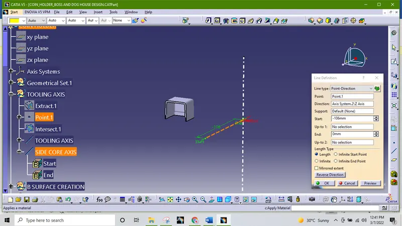
The dog house has an open face that’s why we need a side core axis for the injection molding process. Thus, it will need a separate tooling axis. Here we just made a tooling axis perpendicular to the earlier tooling axis which the direction of open face of the dog house.
PROCEDURE OF SCREW BOSS DESIGN
First, we extract the surface from the bottom of coin holder then take a point at the center and draw a sketch of two circle.
We have considered that a screw boss is M6 screw hole the hole diameter is 5.2mm. As the screw boss thickness should be about 40% or less than that of the normal wall. We take screw boss outer diameter to be 8.2mm (5.2+1.5+1.5)
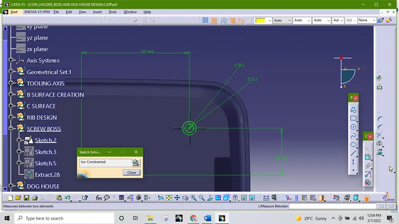
Created a new part body, after that extrude the cylinder using pad command up to 12mm and giving draft inner and outer wall with respect to tooling axis 0.5mm.
For the rib part we can copy and past the same sketch for use. Using pad command extruded the sketch and thicken it by 12mm then apply draft all the vertical wall of the ribs as per design rule. Now apply fillet 0.25mm each edge.
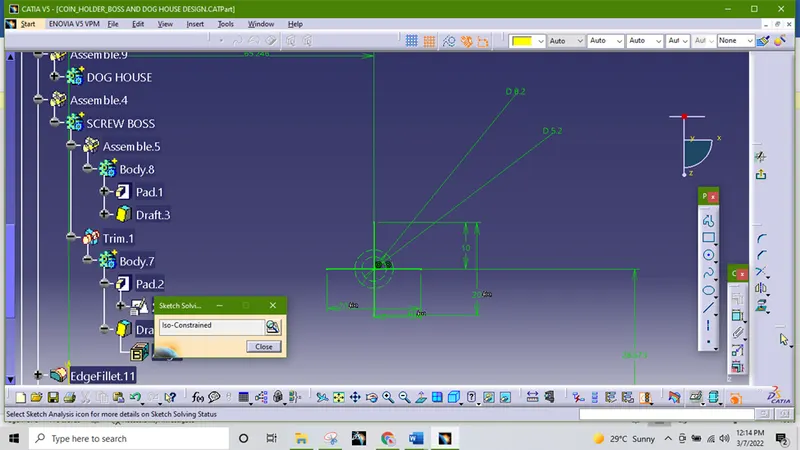
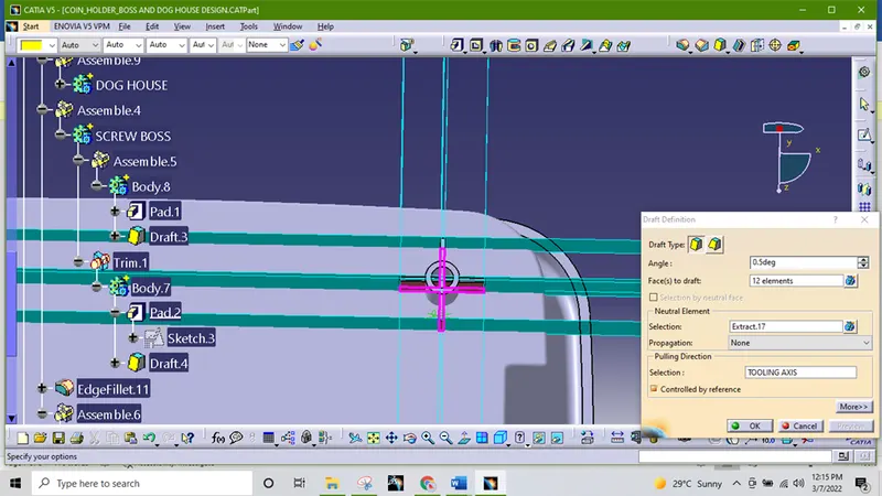
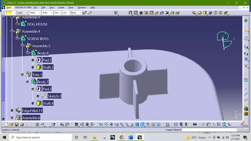
Then copied the screw boss and paste it separately then translate it on suitable coordinates. And assemble to the main body.
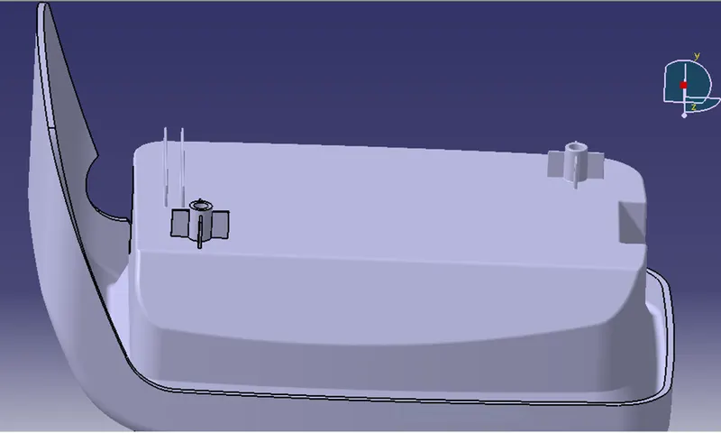
PROCEDURE OF DOG HOUSE DESIGN
First, we deactivate the screw boss For dog house design extract the bottom surface from the class A surface. And offset it by 2.5mm create a point. Then create a rectangular sketch and make one end construction
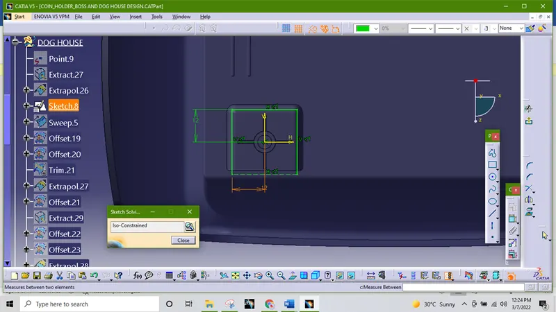
sweep the sketch with draft angle of 1.5degree and height of 21mm. 1mm extra for trim convenience later on. Then offset the base extract upward by 20mm and trim with the sweep to get trim output as below image.
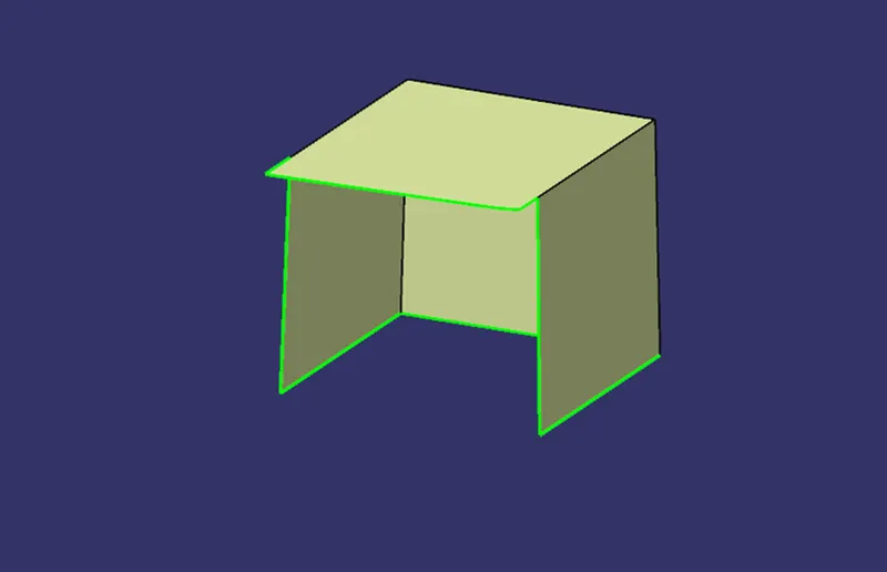
After that thicken it by 2mm
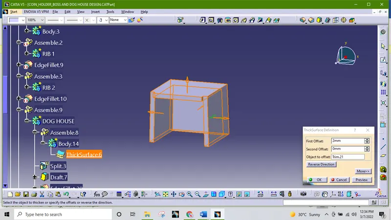
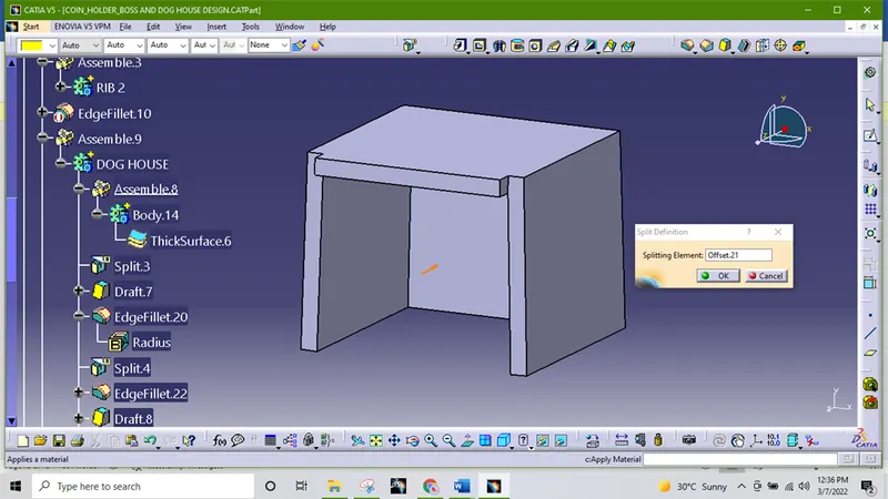
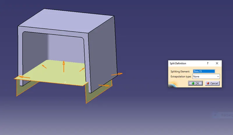
To get the perfect shape we take extract and offset it 22.5mm and split it to body.
Now we need to get the side core tooling axis as the dog house will not cleared in mold ejection through main tooling axis. Create a line using parallel to z axis.
Now provide draft 0.5mm to the inner wall with respect to the tooling axis.
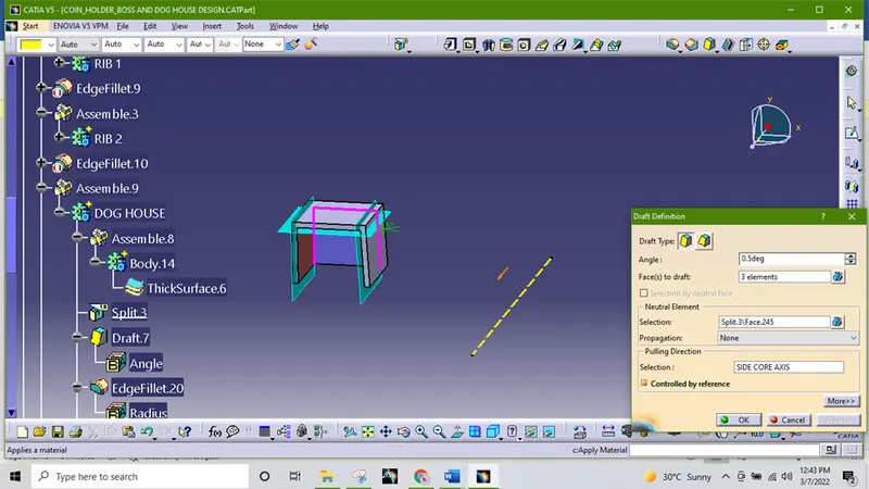
The edge fillet on the dog house inner side 1mm.
The height of the inner house is given as 4mm whereas design parameter 3-6mm. To achieve the C value in the dog house extract the inner face of the dog house and made an offset of 1mm (2.5*.4).
After that we extrapolate the offset and base offset, trim it in required shape. Give the edge fillet of .5mm.
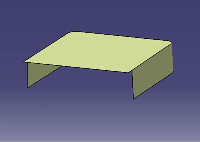
And then split it with dog house to get B and C section.
Drafted the cut section by 0.5mm
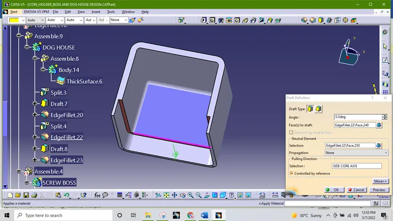
Edge fillet are given the inner side as 1mm.
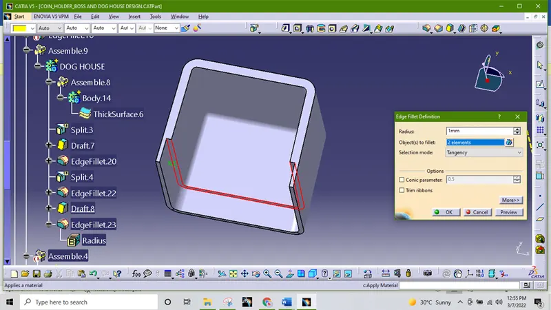
Then we need to add part with the main part with the help of Boolean assemble operation.
We want a screw boss top of the dog house we can translate the screw boss. Translate it using translation command to the appropriate point using coordinate system.
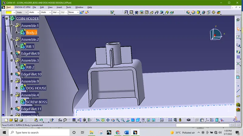
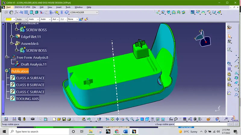
DRAFT ANALYSIS-
- Final plastic parts are the nominal draft angle is 3 degrees but even 7degree is allowed for the subassemblies like ribs and slots.
- Insert< Analysis< Feature draft analysis
- First the compass is moved to the part which used to define the tooling axis new current draft direction then lock the draft direction using the lock icon.
- The color of the chart indicates the draft if the color is indicated that means the part passes and used for further operation.
- By using the analysis under the running point icon, we can check draft angle at the various surface of the component.
- If the surface satisfied the draft angle, then it shows the green color if not appears in red color.
Here change the draft angle 1.45 degree since the draft provide to the dog house 0.5mm.
Draft analysis with main tooling axis
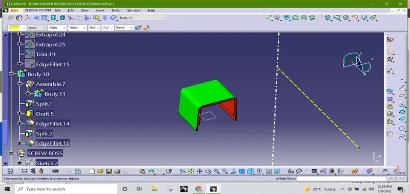
Draft analysis with side core axis
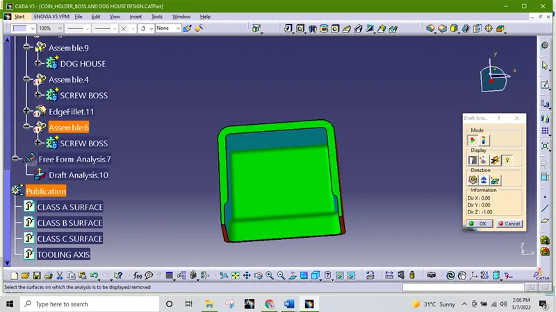
DRAFT ANALYSIS OF SCREW BOSS & DOG HOUSE
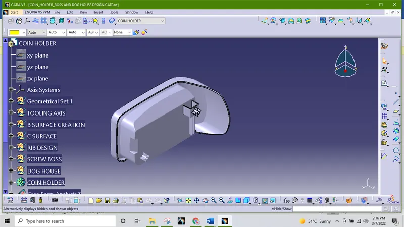
DESIGN VIEW
ISOMETRIC VIEW
FRONT VIEW
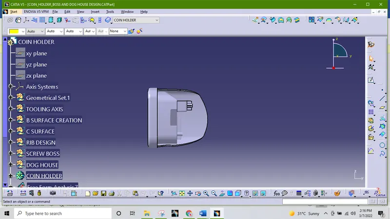
RIGHT SIDE VIEW
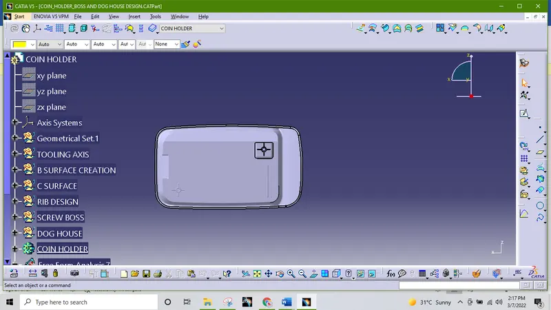
TOP VIEW
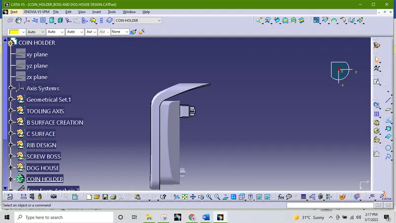
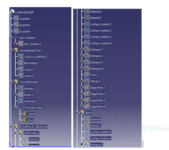
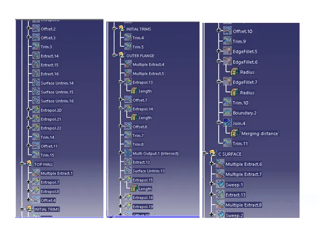
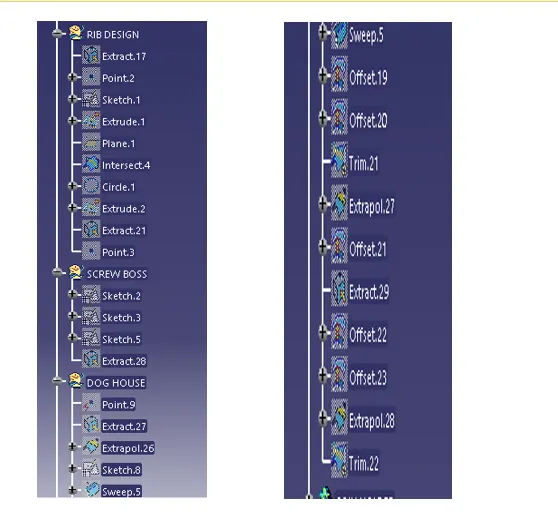
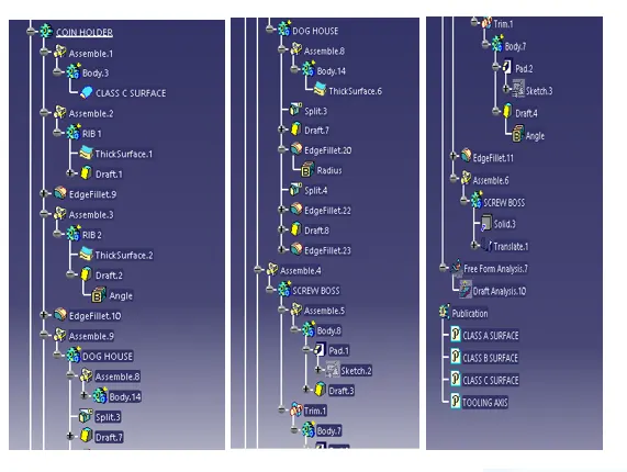
TREE
CONCLUSION- Finally we have created the boss and dog house for coin holder, considering the design rules and performed draft analysis on it.