Week 9 - Attachment Feature Creation - Challenge 2
WEEK-9 CHALLENGE-2
SCREW BOSS AND DOG HOUSE DESIGN
AIM
To create the screw bosses and the dog house for the coin holder component design following the design rules.
THEORY
SCREW BOSS
Bosses find use in many part design for points of attachment and assembly. The most common variety consists of cylindrical projections with holes designed to receive screws, threaded inserts, or another type of fastening hardware. Bosses generally serve two purposes. Their primary use is to strengthen holes or slots in the surface of the plastic part. Bosses reinforce the fracture-prone features like screw holes, penetrations, or mounting slots without impacting the cost or looks of a design. The secondary use of bosses is to create points at which the assembled product can be fastened together.
DESIGN RULES FOR SCREW BOSSES
The design of bosses is critical in injection molding. As with all injection molding, shrinkage is a significant consideration. Shrinkage affects the bosses then they might not align properly, causing delays in assembly.
Important design rules followed by most of the OEMs:
Draft
The most common design rule for any plastic component manufactured by injection molding is the draft angle because; it eases the ejection and improves the tool's life. For the screw boss design, the minimum draft angle to be given to the outer and the inner surfaces is 0.5 degrees and provided in the direction of the tooling axis.
Thickness
The thickness of the boss should be 60 percent or less of the part's nominal wall thickness to minimize sinking.
W ≤ (0.6 x T)
Diameter
The diameter of the outer surface of the screw boss must be twice that of the inner surface, which consists of screw threads to accommodate for tooling device.
D= (2 x d)
Height to diameter ratio
The height of the screw boss and the diameter must be in the ratio of 3:1 to minimize the plastic defects and improve the design.
Depth of the hole
The inner hole which accommodates for screw can be extended into the wall of the component, and the maximum depth up to which this hole can penetrate is equal to 30 percent of the nominal wall thickness.
Optimal fillet radius
The maximum radius up to which a sharp edge can be filleted at the base of the screw boss is observed to be 0.25mm.
The placement of the screw boss close to the sides of the component must be avoided because it directly affects the surface by causing sink marks. The screw boss feature is supported by creating ribs as the screw boss alone is not strong enough.
DOG HOUSE
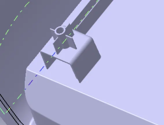
It is embossment for the screws to attach one plastic component to another plastic component when the screw boss is to be placed at a height from the component surface and when the direction of the screw boss is not the main tooling direction.
DESIGN RULES FOR DOG HOUSE
Draft
The minimum draft angle given to the outer surfaces of the dog house is 1.5 degrees in the main tooling direction and 0.5 in the side tooling direction to improve the shrinkage.
Thickness
The minimum wall thickness for the dog house component other than at joining surface is 2mm. The intersection between the dog house and the main element should be 40 percent or less than the nominal wall thickness, and the height difference between the inner surface of the 2mm thick wall and the outer wall of the main component should lie between 3 to 6mm.
Height
Height/ projection distance from the base surface depends upon the assembling point of the plastic components.
Filleting radius
The optimal fillet value for the inner surfaces is 1mm, and that of the outer surface becomes 1mm plus the thickness value (2mm). The minimum fillet value at the surface base is 0.25mm.
PROCEDURE
DESIGN OF SCREW BOSS
Given the thickness of the coin holder to be 2.5mm
Creating the inner and outer surfaces
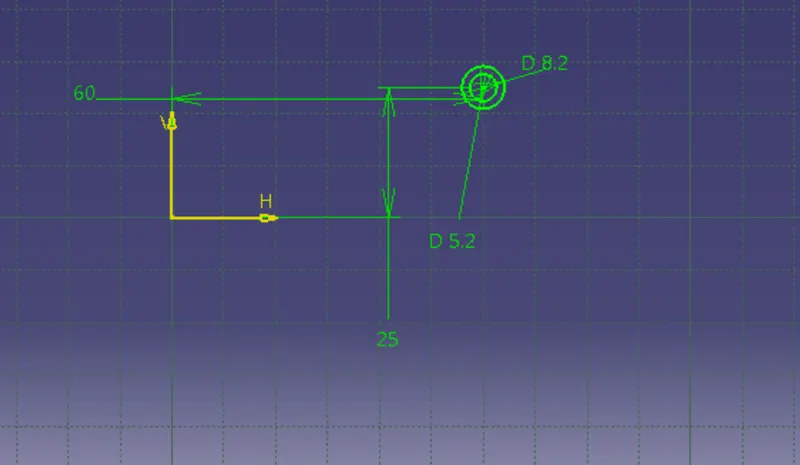
Creating a sketch with concentric circles in the outer plane of the base with the inner diameter value as 5.2mm and the outer diameter can be calculated as:
Outer diameter (D) = inner diameter+ 2x (0.6 x wall thickness) = 5.2+ (1.2 x 2.5)
D= 8.2 mm
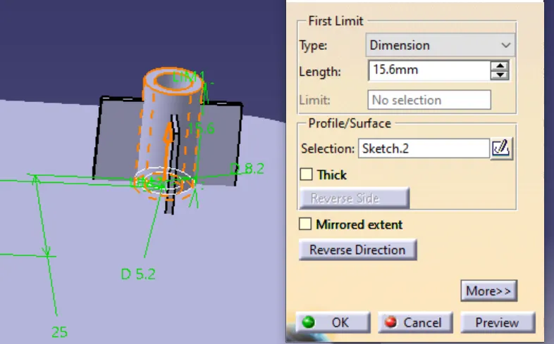
This sketch is padded up to a height of 15.6mm from the base along the tooling direction.
Giving the draft to the surfaces
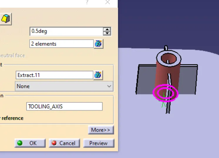
The outer and inner cylindrical surfaces are drafted along 0.5 degrees from the tooling direction, and the direction has to be ensured.
Creating the ribs to support the screw boss
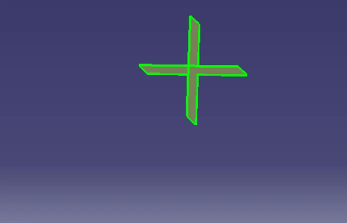
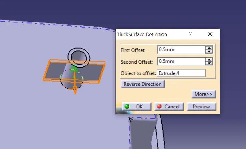
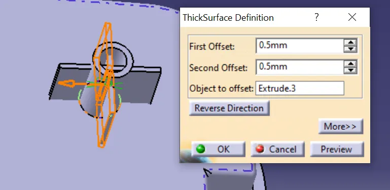
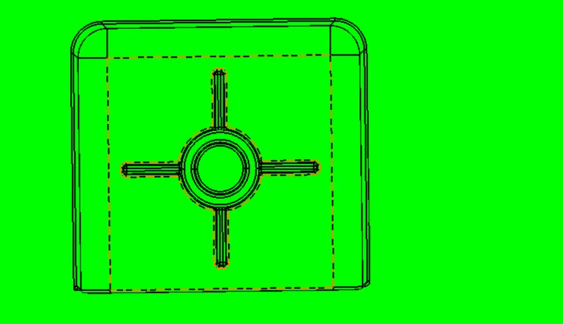
A positioned sketch is created by taking the 3D screw boss elements as reference geometry, and two lines at 90 degrees to each other through the midpoint of the hole are generated, and then these lines are padded up to 12.5mm and are made 1mm thick.
Assembling the feature to the main body
The screw boss assembly is created by applying union trim operation to the rib and the outer surfaces of the screw boss. This assembly is now joined to the main body, and all the edges are filleted by the optimal radius value of 0.25mm.
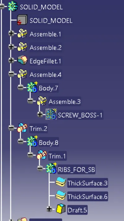
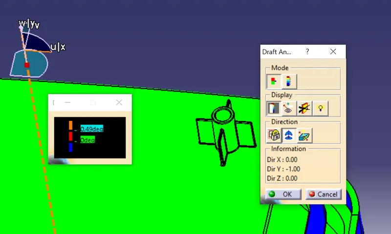
Draft analysis
Finally, the draft analysis of the body is performed in the main tooling direction to inspect the minimum draft condition for all the surfaces.
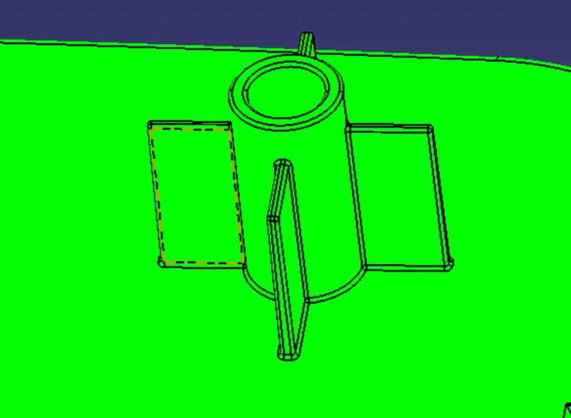
DESIGN OF DOG HOUSE
Creating the side and upper walls
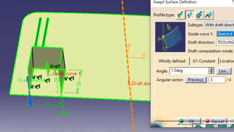
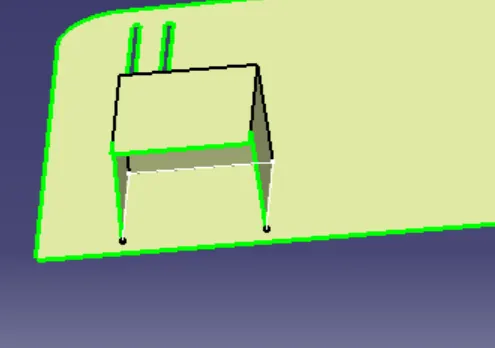
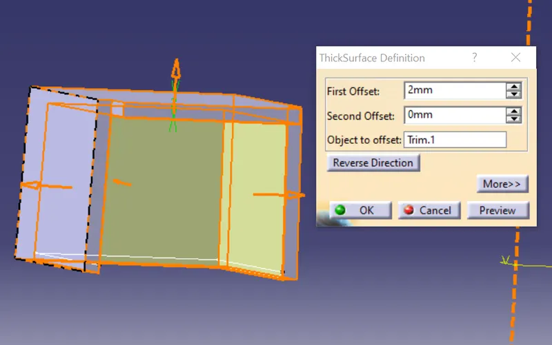
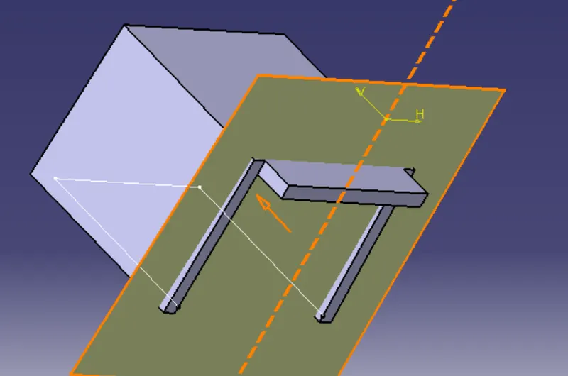
The location of the screw boss is identified. A rectangular sketch is created on the base surface with the center of the hole, and one edge of the rectangle is converted into a construction element. The projection is made from the three-edged rectangle at an angle of 1.5 degrees from the tooling direction using the sweep command to obtain the side walls. Now, the upper wall is obtained by offsetting the base surface by the given height. The sidewalls are then extrapolated and trimmed off with the upper walls to get the inner surfaces of the dog house. These inner surfaces are thickened outward by 2mm to obtain a solid body.
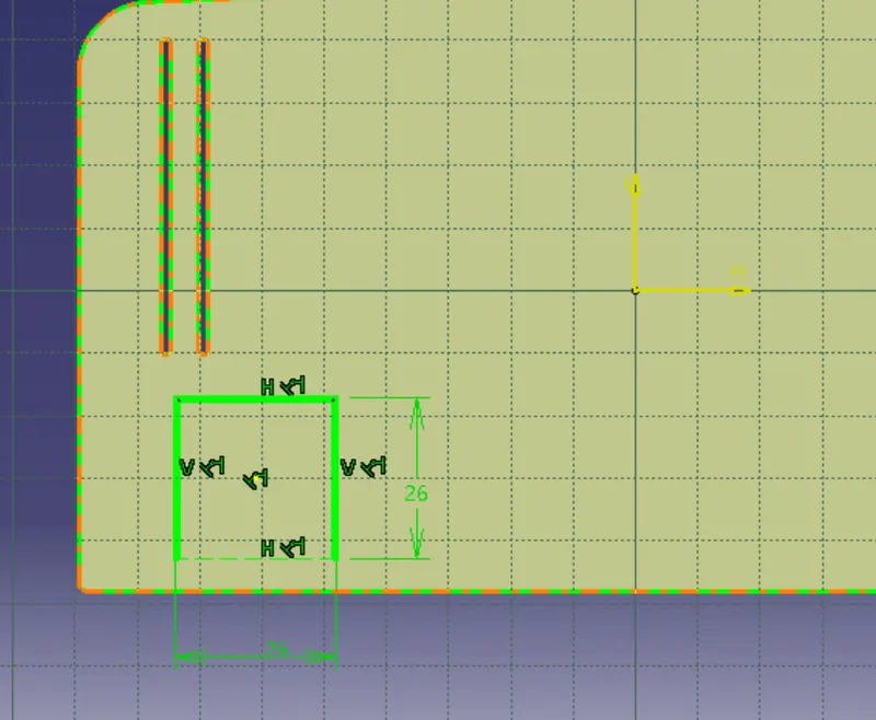
Drafting the inner surfaces
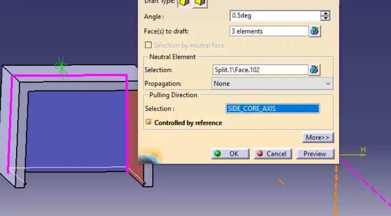
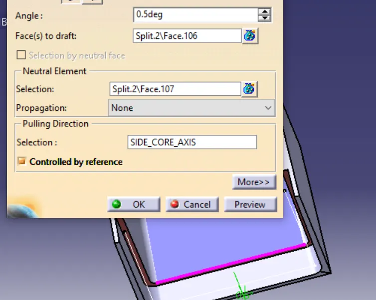
A side core tooling axis is created in the horizontal plane for tooling the inner surfaces. The inner surfaces of the dog house are drafted by 0.5 degrees with this side tooling axis.
Trimming
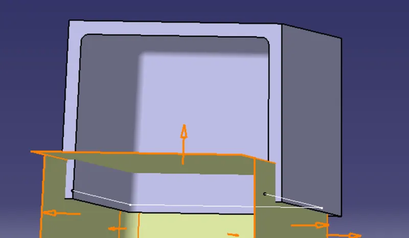
Uneven surfaces in the front of the part body are trimmed off by splitting the body with the offset surface of the extract of the dog house base. Now the inner surface of the dog house is offset by 1mm (since C = 40 percent of nominal wall thickness), and the base surface of the main body, which is extracted and untrimmed, is now offset by 4mm (B). These offset surfaces are extrapolated and then trimmed to get the splitting element to cut the inner surfaces, and the splitting operation is performed.
Filleting and Assembling
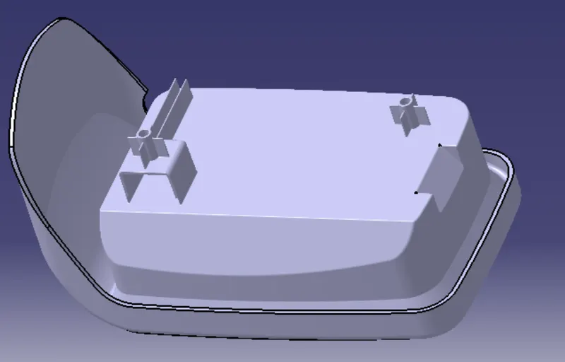
Inner and outer edges are filleted by taking the optimal fillet values as 1mm and 3mm, respectively. Now the dog house body is assembled to the main body. The screw boss, which is supposed to be facilitated by the dog house, is created by following the design rules and procedure mentioned above.
Draft analysis
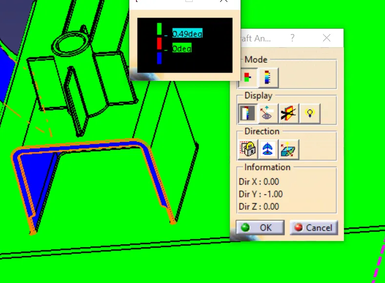
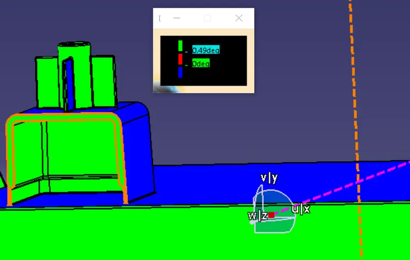
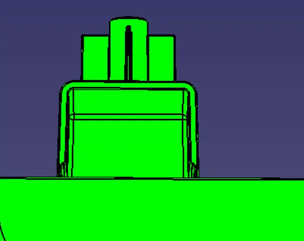
This feature's draft analysis is performed in two different tooling directions, i.e., main and side tooling axis.
FINAL ASSEMBLY