Week 9 - Attachment Feature Creation - Challenge 2
Aim: To Create the boss and Dog House for the Centre console coin holder.
PROCEDURE
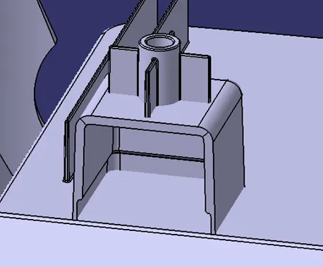
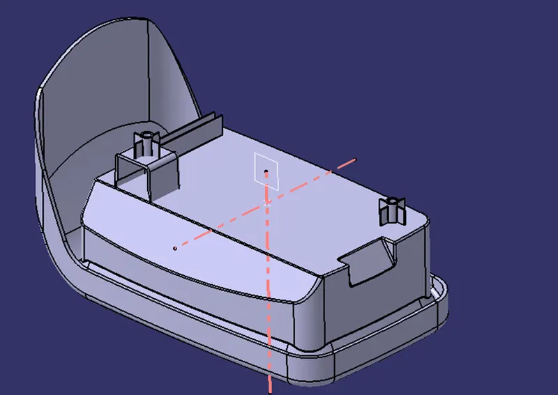
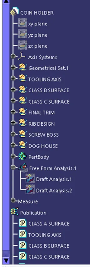
Using the previous Model of Center Console Coin Holder the attachment features are created over it. For that process first the screw boss is created after which the dog house is made using the design rules.
CREATION OF SCREW BOSS: -
Screw bosses can be reinforced with ribs or gussets for added strength and durability. As we mentioned a boss should not be next to exterior walls, but you can use coring ribs to keep it connected to the part's exterior wall without risking sink.
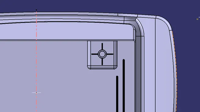
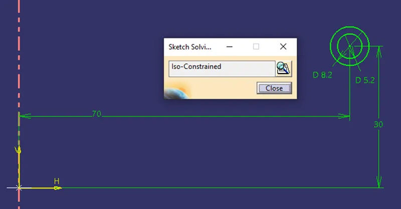
First step is to create sketch for the Screw boss slot and its ribs to strengthen it with Iso-Constrained.
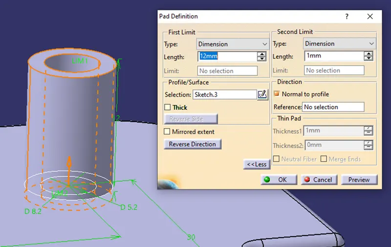
Then thicken the sketch for 1mm.
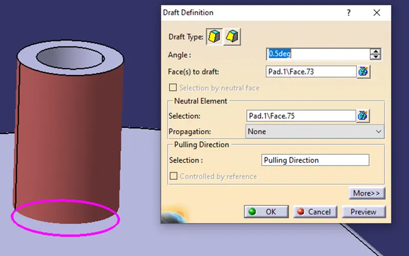
Next will be drafting of the screw boss with minimum of 0.5 degree.
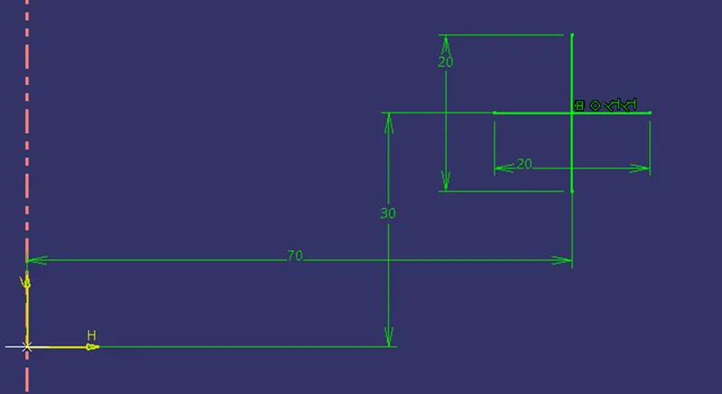
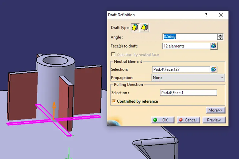
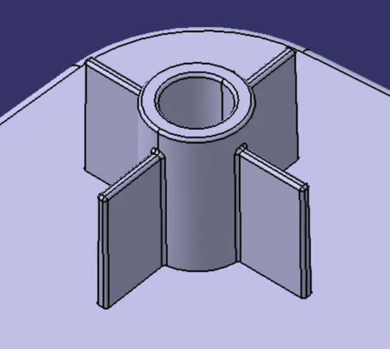
After that use translate to move the boss so that it can be placed on the Dog House.
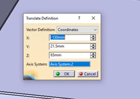
For the addition of another boss use Copy, Paste Special and Translational Movements along X,Y,Z Axis ( Positive and Negative).
CREATION OF DOG HOUSE:
First the dog house sketch is drawn with Iso-Constrained.
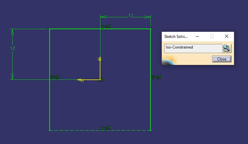
Using Sweep create surface .
Extract base and offset to make the roof of the dog house.
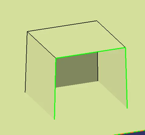
Using thicken option thicken the surfaces.
UNDER CUT OF DOG HOUSE:
Creation of this inside the dog house so that Sink mark and Flow line should not appear on the surface because the thicknes of the dog house.
Extract the inside of the Dog House and offset it for 1mm.
Offset the base surface for 4mm.
Trim with the offseted base surface.
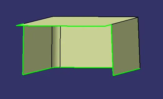
The under cut of the dog houde is drafted.
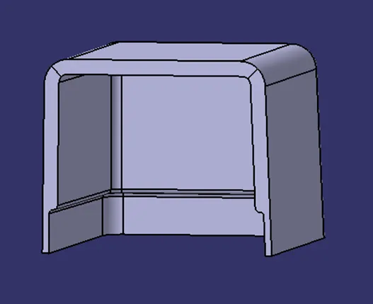
DAFT ANALYSIS
The finished part is then analyzed to detect if the drafted part will be easily removed from the injection molding.
Draft Analysis option in CATIA is enabled through Insert> Analysis> Feature Draft Analysis
Draft Analysis Procedure:
The part created has to be changed to material mode in display frame.
Then by enabling compass definition the axis system is pan along the direction of the part and aligned in line with the tooling direction.
Lock Direction is applied that fixes the compass and then the mode dialog box is formed by snapping at any point on the part.
The Color Codes are classified and Draft Angle are applied.
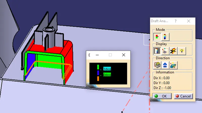
Then the Running point analysis is used to hover around the part to analyze the permissible draft angles and the analysis is saved.