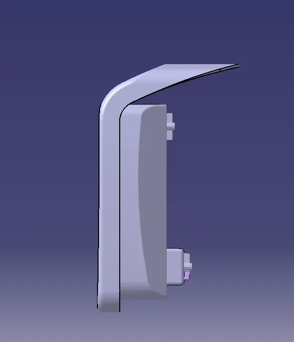
Week 9 - Attachment Feature Creation - Challenge 2
Objective:
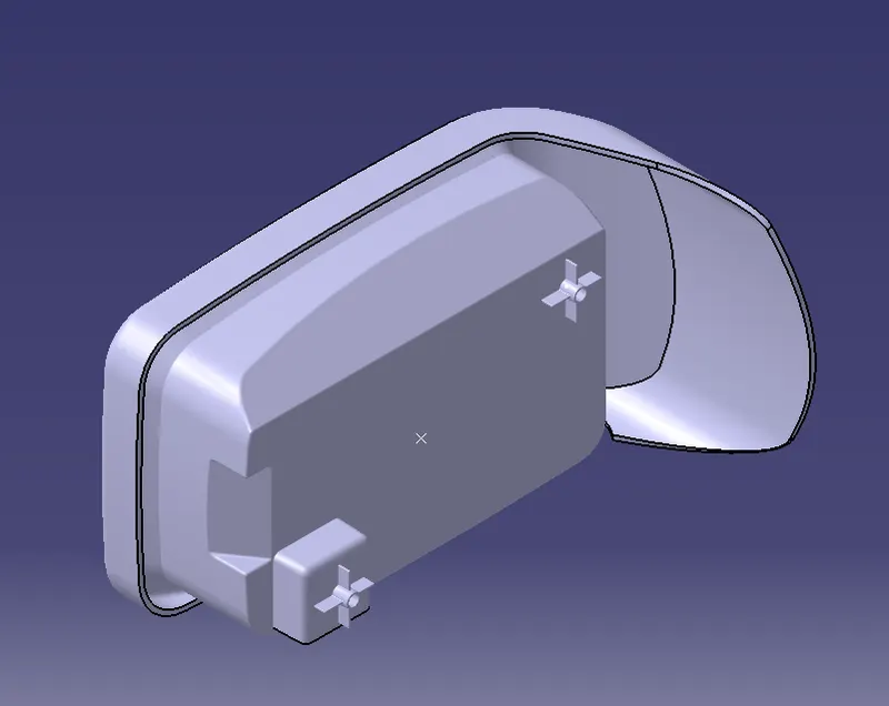
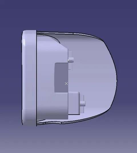
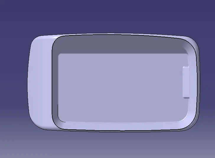
Create the boss and Dog House for the Centre console coin holder considering the design rules mentioned in the video.
Answer:
1) Draft Analysis
Draft analysis is done to ensure that the designed part is manufacturable based on the draft conditions applied. It is done to ensure the proper ejection of the component from dies(for metals) or molds(for plastics). The basic idea is to ensure that the tooling axis has to be created in such a wat that it has no parallel surface profiles of the component so that the ejection of the components can be ensured . Tooling axis is the axis along which cavity and core are closed and opened .
2)Procedure for creation of tooling axis
Step 1: Import the model and check for surface continuity and connectivity using Join tool .Ensure there is no surface gap
Step 2: Insert a geometrical set . Exctract the base surface and create a point at centre of the hole using point on circle option from point tool. Look for suitable axis to create a tooling axis so that all faces clear tooling .
Step 3: Create an axis system without current option ticked at the above point. Create an intersection with zy plane from axis system and above surface as reference .
Step 4: Here we can observe that there all multiple surfaces with 0 draft angle . Hence it will not clear any tooling axis . Hence we can create a tooling axis normal to the surface . Use create line using point and direction to create the tooling axis .
Procedure to check for Draft analysis
1)Once the tooling axis is created , publish it and the component using Publication from tool option .
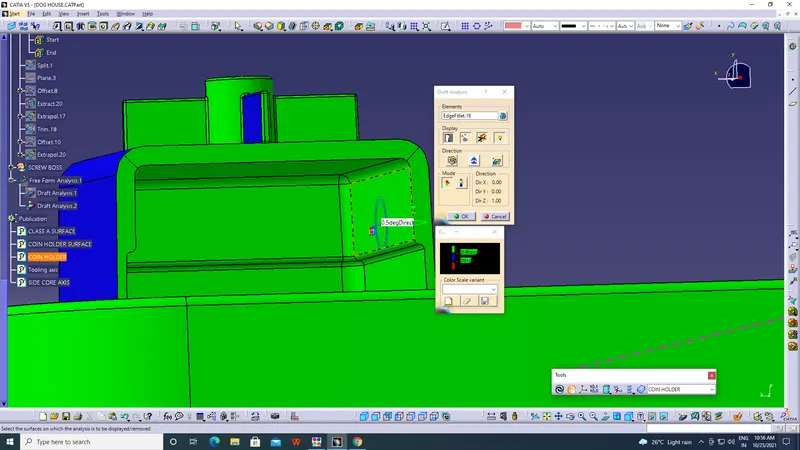
2)Insert Feature draft analysis option from insert tool bar
3) Change the view option to customize view parameters and click on material option under shading .
4) Now click on the axis option from Draft analysis tools , allign it with tooling axis and click on lock option to lock it .
5) Change draft angle value to 3 degree . Click on quick analysis mode to display feature according to given color scale . Check from all views to ensure the draft analysis is cleared .
Here we can observe that the tooling axis does not clear the draft analysis . This is because the class A surface was created without providing minimum draft angle of 3 degrees.
Hence we have created tooling axis
Procedure to create side core axis
1) Create a line using point direction option . Select above point and z axis as direction.
2)Repeat step 1 to 5 in above procedure instead of 3 degree , use 0.5 degree as Draft value .