Week 9 - Attachment Feature Creation - Challenge 2
Creation of Door trim with Dog House
Aim:
To Create the Door trim along with Dog House from the given Class A surface.
Procedure:
Step 1: Class-A Draft Analysis
First check the given Class A surface which clears the draft analysis or not.
Step 2: Creating Tooling Axis
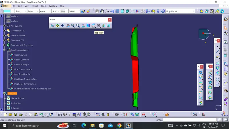
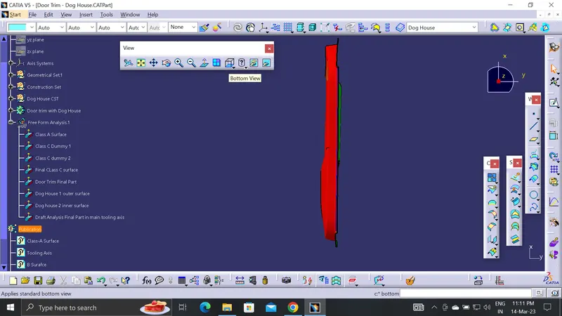
For checking the draft analysis need to create the "Tooling Axis" is our first step. Therefore we check which direction (X, Y & Z) will helpful to create "Tooling Axis"
In X-direction the view of the given surface is not clear, in that view point we can't create the door handle
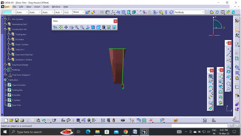
In Z-direction also we can't see the full surface
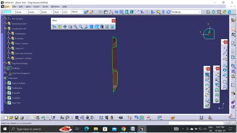
In Y-direction, we can able to see the complete surface and it's easy to produce the part along Y-direction. Hence we consider that "Y" is our tooling direction
Tooling Direction – "Y"
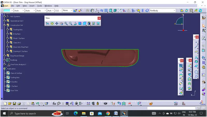
Step 3: Extract the flat surface in the given Class-A surface and using Point command > On Surface we mark the point on the middle of the given surface.
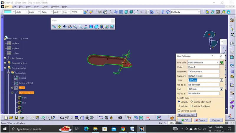
Then using Line Command > Point and Direction, select the Middle point of the surface and direction is "Y". Rename the line as "Tooling Axis".
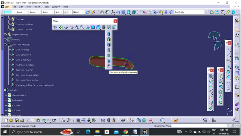
Step 4: After creating the tooling axis, now we are going to perform the Draft analysis for Class-A surface. First change the View mode option as Customize view parameter and select the material option.
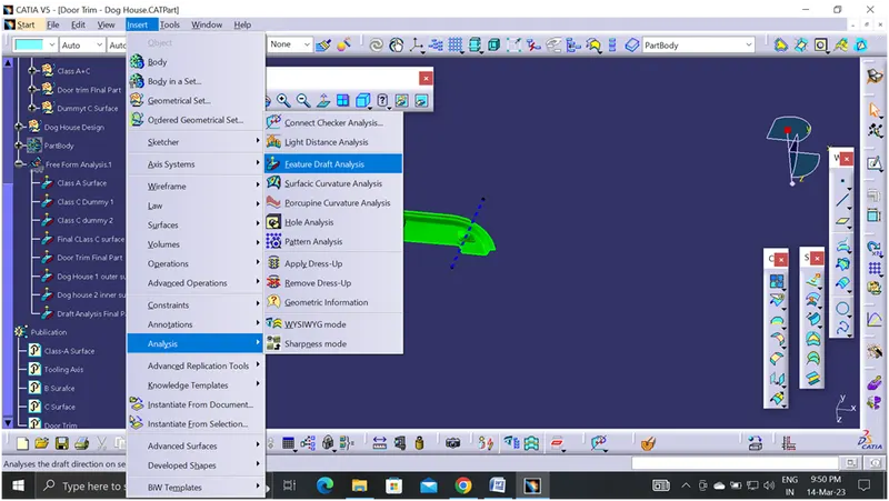
Step 5: Select Feature draft analysis command, Click the compass icon, drag and place the compass along the Tooling direction and lock it. Then select the Class-A surface, and inverse the draft. To enable the Colour scale icon under the Display tab.
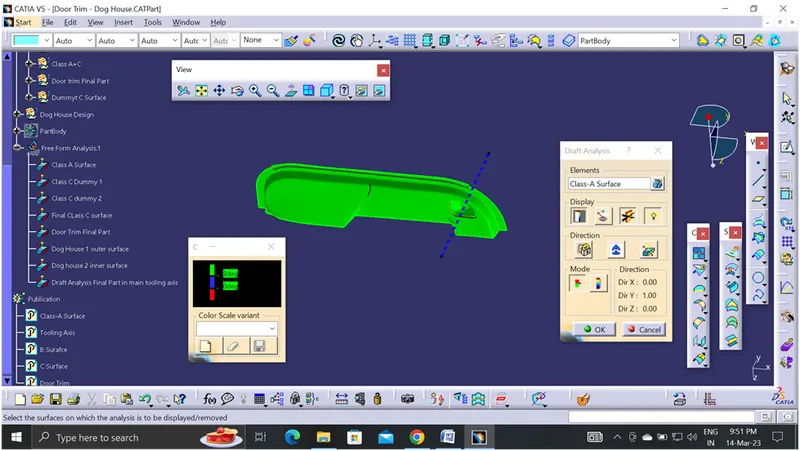
Draft Angle for Class-A surface – 3 degree.
Step 6: After the draft analysis, need to create the B surface. Usually in plastic parts the B surface is 2.5mm distance from the class-A surface.
Offset value of B surfcae – 2.5mm
Offset the given class a surface at an distance of 2.5mm. Some portion is missing while performing the offset.
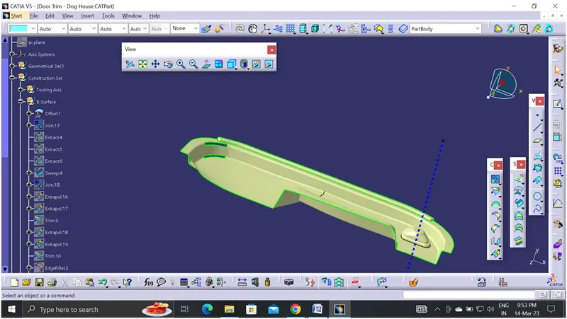
Using Multisection command we recreate that part and join with the offset surface. Now get the B Surface
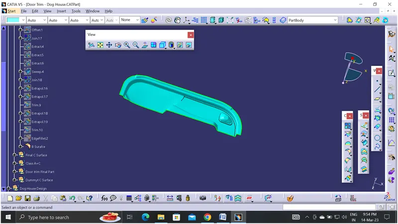
Step 7: Creating C Surface
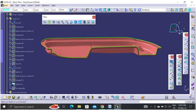
For creating the C surface, take a reference from the A-surface and using sweep command > With Reference surface. Select the entire Class A boundary and draft angle is 90 degree at a length of 9mm.
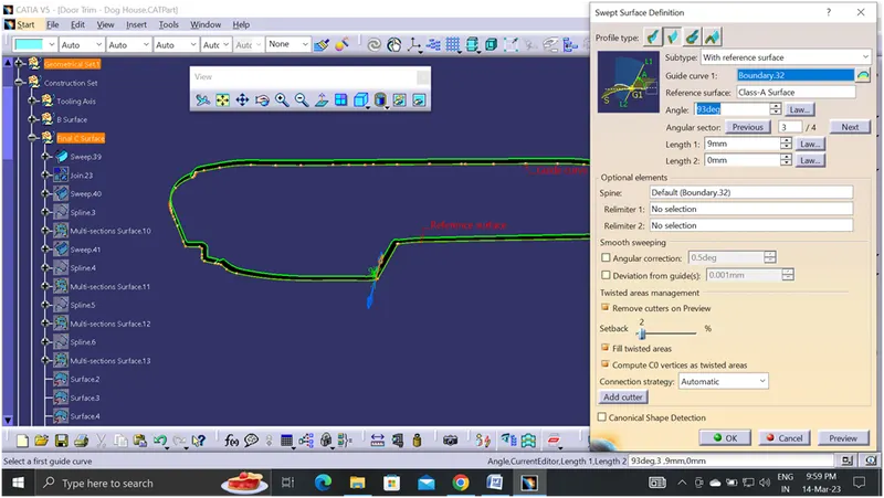
Now check the draft analysis for reference whether the created part is right or wrong. On that note the draft analysis check failure at some portion.
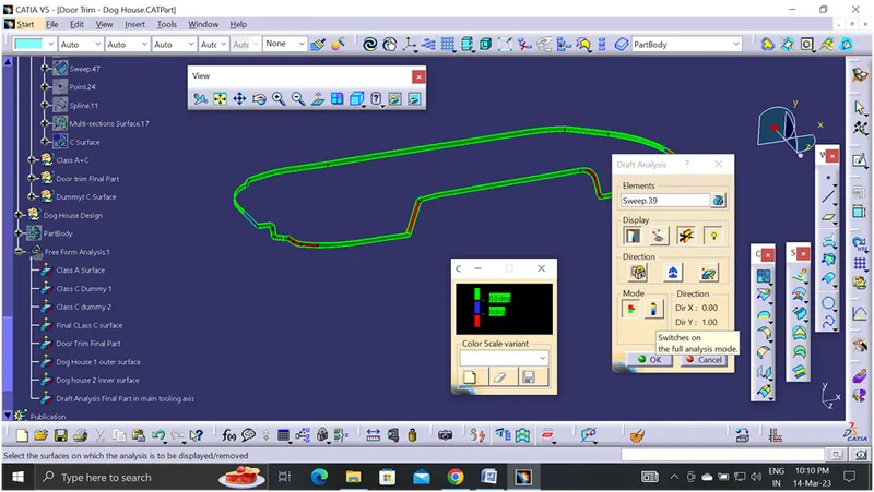
Step 8: Now using Join command to join the sweep and Class A surface, and select the Sub – element to remove tab remove the marked faces.
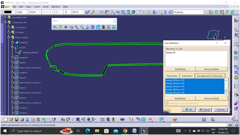
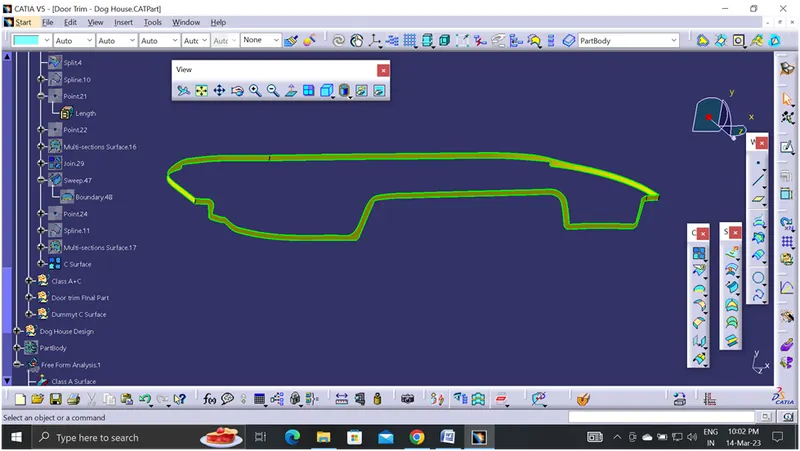
Why because the particular surface is perpendicular to the Tooling axis, so in order to clear the draft analysis we have to create the surface in Sweep > Draft direction Technique.
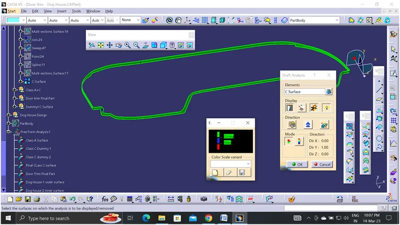
Now to check the draft analysis for Class-C surface it's clear at an angle of 0.5 degree.
Finally using trim command to joins the class A & Class C surface
Step 9: Creating final part (door handle)
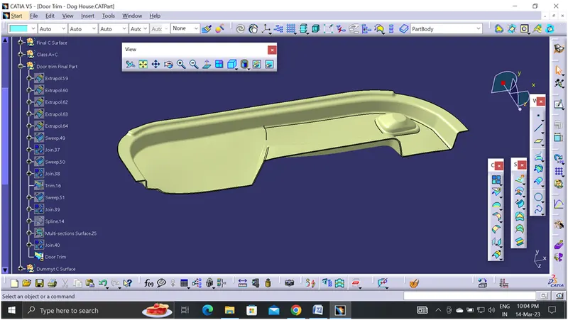
Extrapolate the Class B surface and trim that surface with Class A+C surface to get the final part. Now check the part is a closed one or not? Select the Boundary command and pick the final part, error message will pop-up, this mean the given body is completely closed no open boundary. Now name it as Door trim.
Step 10: checking draft analysis for final part.
Follow the same step for the class-A surface draft analysis.
Now change the draft angle is 0.5 degree it clears the draft but however some portion have no draft.
To overcome this problem remove such portion and recreate the surface using sweep command using reference surface method. While performing draft analysis increases more number of areas as negative and no draft area.
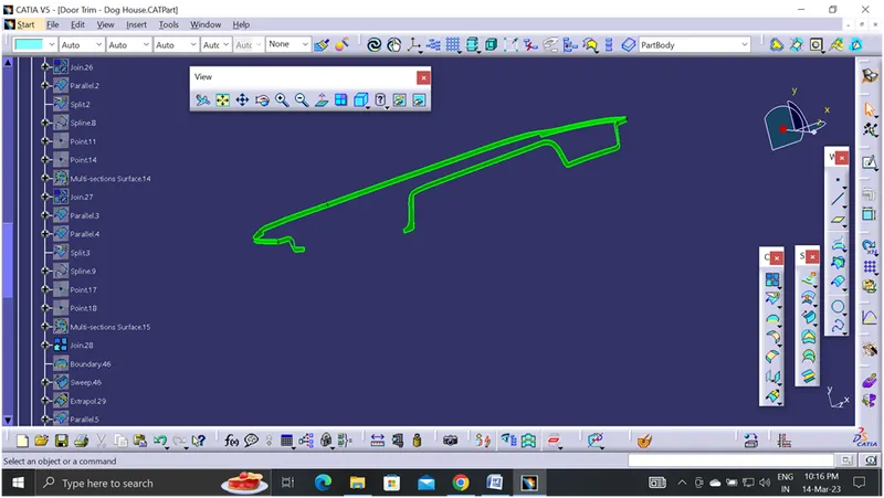
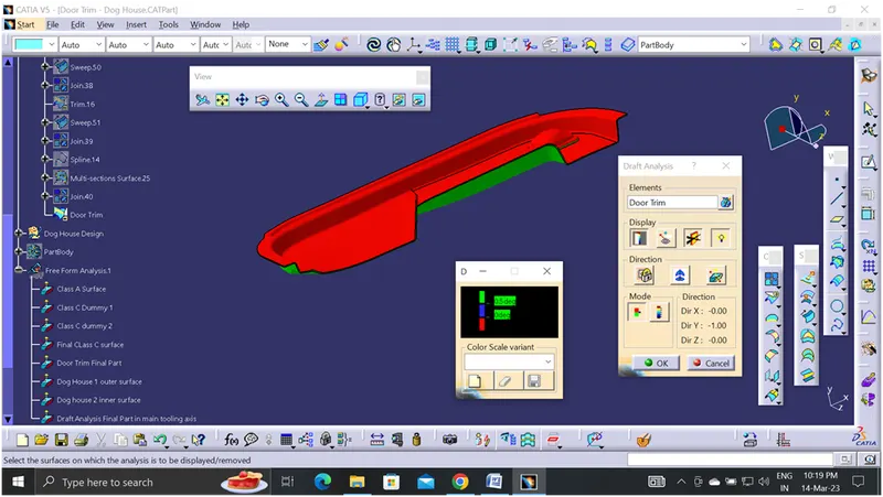
Finally decided the combination of Reference surface method and Draft direction method will give the maximum clearance in the final output. So take this surface as my input and perform the draft analysis at an angle of 0.5 degree.
Step 11: Create Part Body
Go to Part workbench using Close surface command select the door handle final output make it as a complete closed part body.
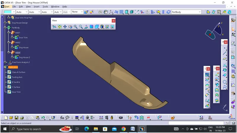
Step 12: Create Dog House
Before creating the dog house we must create the side core tooling axis first. For that take a same reference point of main tooling axis and give the direction in X-direction. Name it as Side core axis.
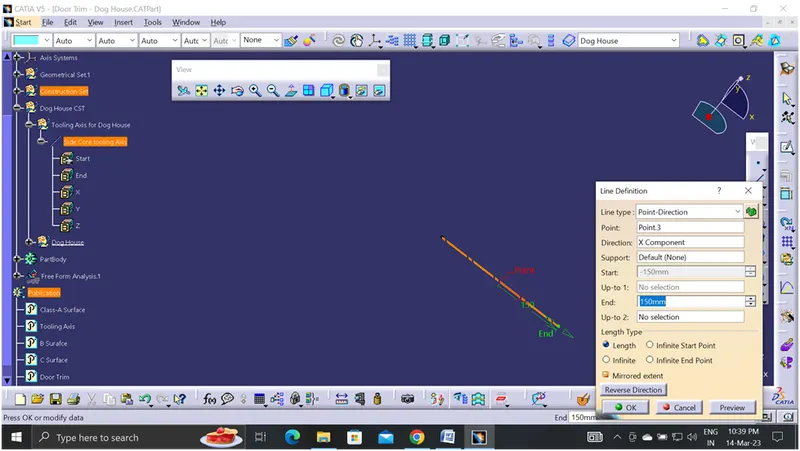
For creating Dog House, should follow some design constrain. Based on this condition ribs created
Condition to create Dog house:
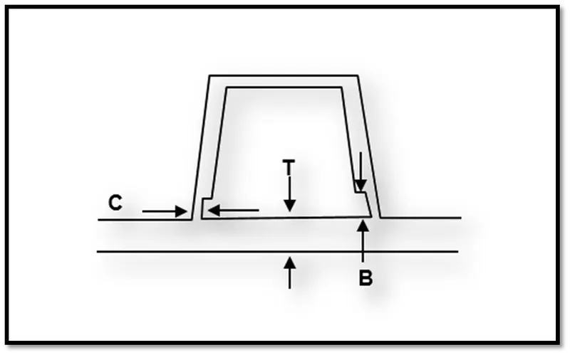
- Doghouse wall thickness at the intersection of the part wall (C) should be 40% or less than the main wall stock (T).
- The height of (B) should be between 3.0 – 6.0 mm
First create a geometrical set and name it as "Dog House", then draw the sketch on the inner side of the part (which mean Part B)
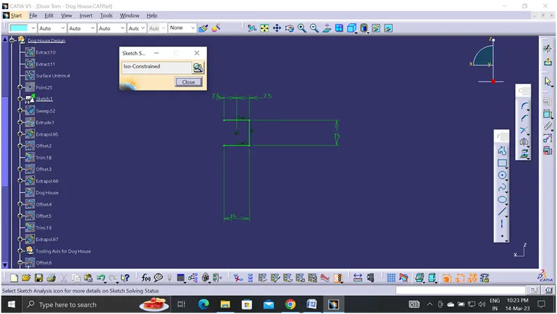
Sweep the sketch at a height of 25mm and draft angle 1.5mm in main tooling axis, and then trim the sweep surface at a height of 20mm.
|
Dog House Height = 20mm |
Then create a Body and using thick surface command thicken the Rib at an amount of 2mm.
|
Dog house thickness = 2mm |
For creating the C & B area, offset the main dog house 1mm outside, why because the C area is 40% of the main thickness of the component
|
C area = 0.4*2.5mm |
|
= 1mm |
Then using draft command option, select all the inner faces of the Ribs and give draft at an angle of 0.5 degree. This is the minimum draft angle for Inner area of the Dog House.
Radius is 2mm is given to the all out sides of the Dog house, and minimum inner radius is 0.5mm. Hence all the conditions are followed to make the Dog house.
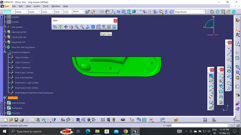
We have dog house in 2 areas so we positioned the second dog house at a range of below co-ordinate area
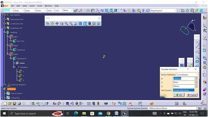
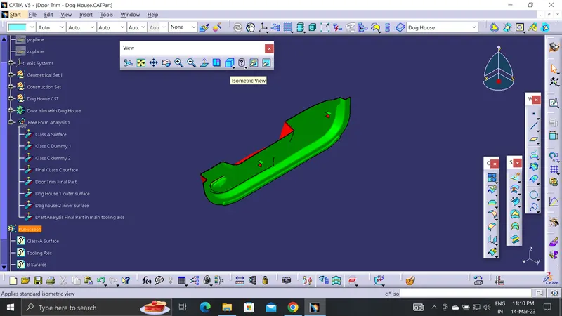
Finally add the two dog house in the main part body and make it as single component. Name it as Door trim with Dog House.
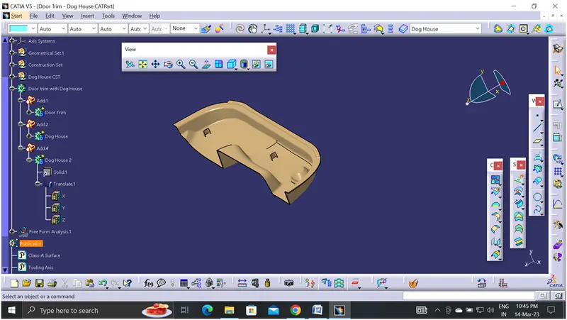
Step 13: Draft analysis for the Door trim with Dog House.
Follow the same set of procedure and perform draft analysis of the end component. Now we clearly see at an angle of 1.5 degree of draft the component no clear the draft analysis.
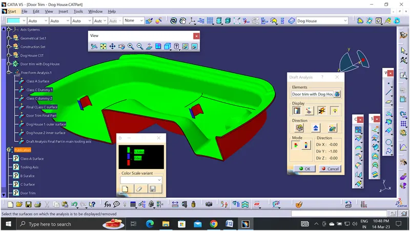
We continuously check and reduce the draft angle for 1.49 degree in main tooling axis the entire part will clear the draft analysis test.
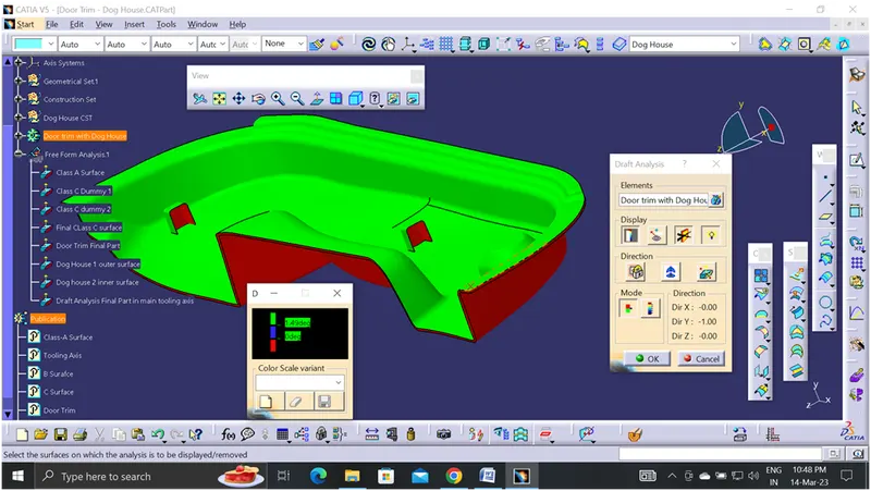
|
Draft analysis for the end product = 1.49 degree |
While check the inner side of the dog house at an angle of 0.5 degree some inner surface not properly clear.
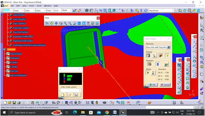
So we give the draft angle of 0.48 degree all the inner surface clear the test
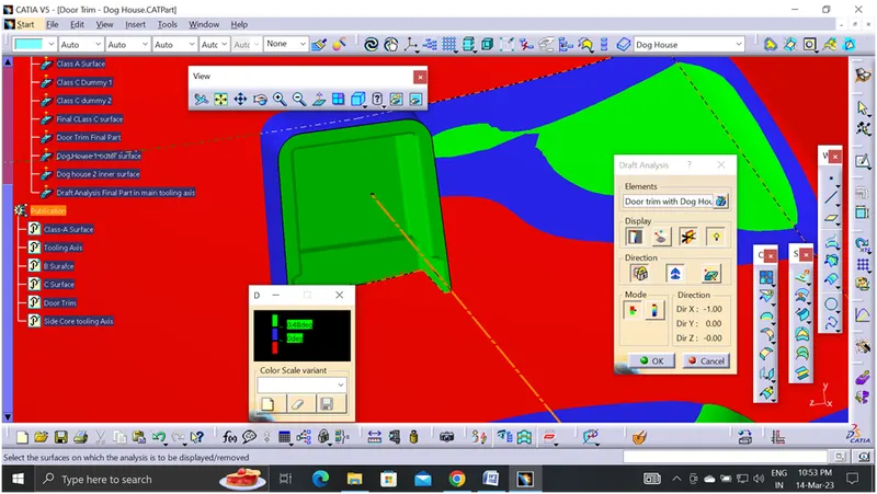
|
Draft analysis of inner surface of Dog house = 0.48 degree |
Conclusion:
- Based on the given Design feature of Class A, Dog House we created the End part Door trim with Dog House.
- Perform the draft analysis in every necessary stage and made necessary changes in the design to clear the draft analysis.
- Dog houses are fixed in the door trim without violating the design constrain.
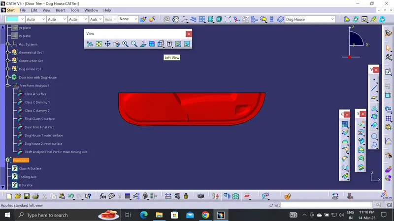
View Mode :