Week 9 - Attachment Feature Creation - Challenge 2
Procedure :
Creating the tooling axis
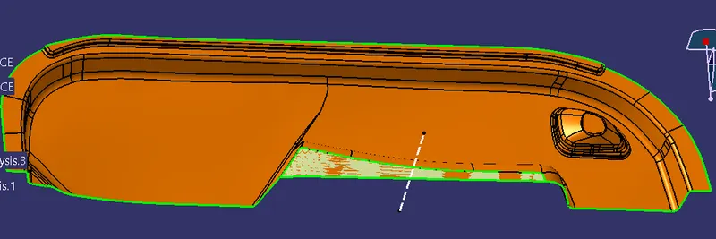
The tooling direction is used to find the direction in which the part is ejected out of the mold or it is the direction in which the core and cavity are moved and the part is ejected.
The draft on the part should be positive in order to manufacture the part easily. The draft angle should be positive with respect to the tooling direction.
- The tooling axis created by following steps
1) It is to select class A surface base to extract.
2) creat point on extract.
3) select point to direction command in line definition on it point.1 and normal to surface.
Draft analysis :
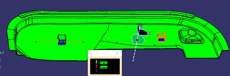
- To perform the draft analysis the view parameters are first set to material mode.
- Then go to Insert >>analysis>>feature draft analysis.
- First, select the axis system and drag the axis system to align and coincide with the tooling axis and lock the orientation. This axis system defines the draft direction according to the tooling axis.
- Switch on the color scale and set the minimum draft value. Here it is set to 3 degrees and it will be displayed in green color. Any draft angle below 0 degrees will be shown in red color.
- Now select the running point tool to measure the draft angle at the various locations and then if all surface passes the draft analysis switch on the light effect that will show the component in green color if the component has the required draft angle.
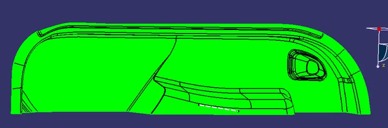
- The final draft analysis shows the green color surface having the draft angle above 3 degrees and red or cyan color shows the draft angle below 0 degrees.
CLASS A
class A is given.
CLASS B SURFACE
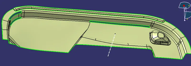
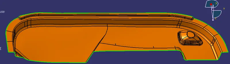
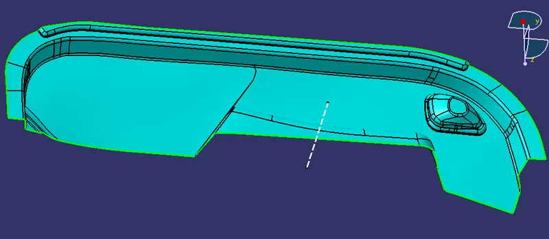
- class B surface is offset to 2.5mm.
- In this some 3 gaps is formed in this we need to mulit-extract on three areas and we can use trim.
- in final class B we need to fillets on 3 areas and the CLASS B IS FORMED.
CLASS C
-
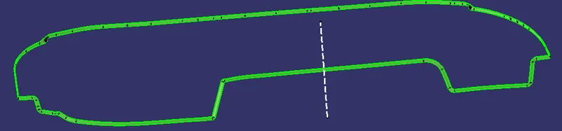
C class is where the thickness of the component can be seen.
-
For the C surfaces, the boundary is extracted from the A surface and then swept with a reference surface in 90.
FINAL JOINT
- C is joined with the A surface.
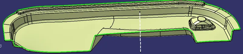
- Lastly,the AC is joined with the B surface to get the final Door Trim component. This obtained surface is then thickened in part design.
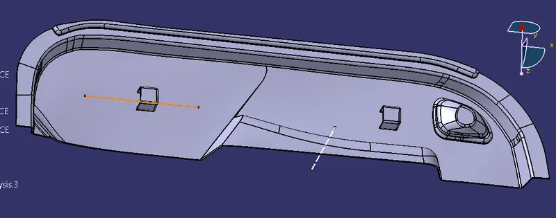
Draft analysis
creation of DOG HOUSES
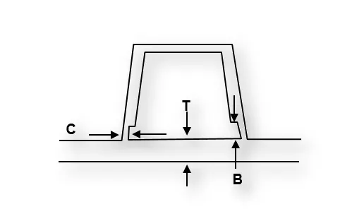
"C" is where the doghouse contacts the backside of the surface
-
Doghouse wall thickness at the intersection of the part wall ( C ) should be 40% or less than the main wall stock ( T ).
-
The height of ( B ) should be between 3.0 – 6.0 mm
DOG HOUSES
- WE TO CREAT SKETCH WITH AND CREAT A PLANE .
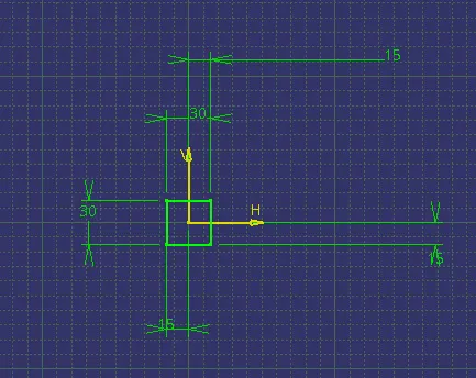
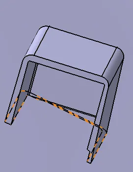
- WE NEED TO CREAT PAD > SHELL > DRAFT > EDGE FILLETS
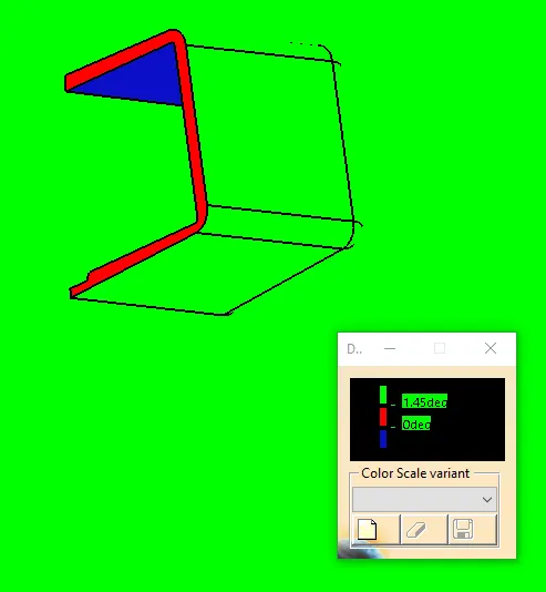
- DRAFT - 1.5DEG , INLET THICKNESS-0.5MM AND EDGE FILLETS IS 3MM OUTER SURFACE.
Draft analysis
- DRAFT IS 1.45 AND GREEN COLOUR IS FORMED.
creation of SIDE CORE
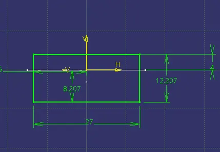
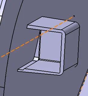
- WE TO CREAT SKETCH WITH AND CREAT A PLANE .
- WE NEED TO TAKE THE X AXIS TO POINT AND SIDE CORE IS CREATED.
- WE NEED TO CREAT PAD > SHELL > DRAFT > EDGE FILLETS
- DRAFT - 0.5DEG ,EDGE FILLETS IS INLET THICKNESS-2MM.
Draft analysis
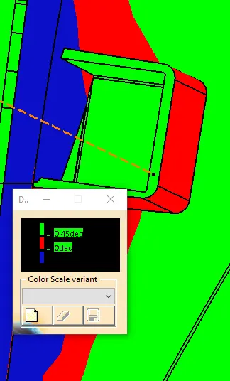
- DRAFT IS 0.45 AND GREEN COLOUR IS FORMED.
FINAL Door Trim component
- AS WE CREATED FINAL DOG HOUSES SO, WE CAN TRANSLATE TO POINT TO POINT .
Draft analysis