Week 9 - Attachment Feature Creation - Challenge 2
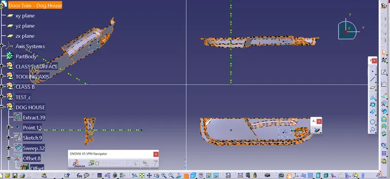
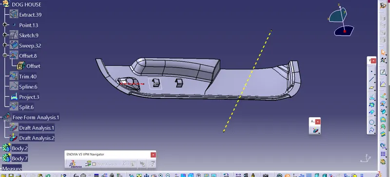
"C:\Users\Chetan\Desktop\Door Trim - Dog House (1).zip"
REPORT :
DRAFT ANALYSIS :
The Draft allows the part to easily eject from the mold. The draft angle is to reduce friction between the core, cavity and part and it also avoid the damages. The minimum draft angle is 0.5 degree and the most common draft angle used in the plastic design is 3 degrees.
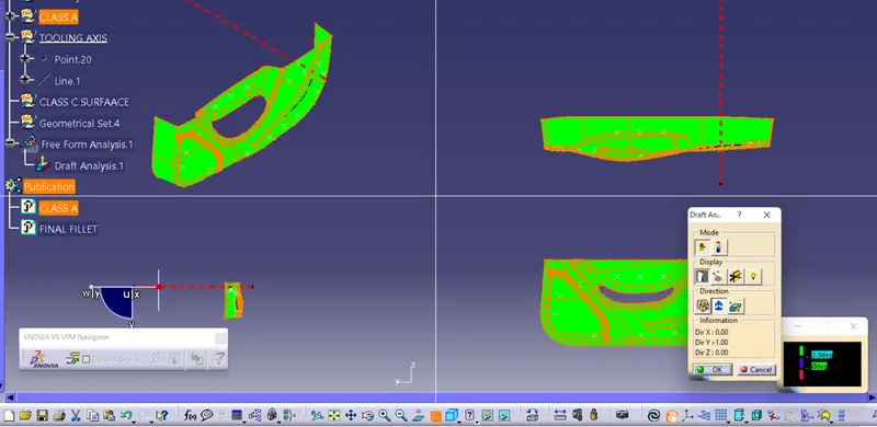
In CATIA the draft analysis is performed based on colour ranges identifying zones on the analysed element where the deviation from the draft direction at any point, corresponds to specified values.
SPETS :
- For plastic parts the Nominal draft angle is 3deg, but even 7deg is allowed for the subassemblies like ribs and slots
- INSERT - ANALYSIS - FEATURE DRAFT ANALYSIS
- First the compass is moved to the part (the compass sholud be placed on the tooling axis) which used to define the new current draft direction, then lock the draft direction using the lock icon
- The colour chart indicates the various condition of the draft angle . the green colour indicates that the part passes and the and can be used for the further operations
- By using the analysis under the running point icon we can check draft angle at the various surfaces of the component
- There are two modes in the Draft analysis quick mode and fully detailed mode .
TOOLING AXIS :
Tooling direction is the main element that to be consider while designing a plastic component. In moulding machine the arrangement is given to open the mould along the direction. It is the direction in which the core and cavity opens.
- First the connectivity between the surfaces to be checked, by using the join option see how the surface is connected and ensure that there are no surface gaps in between the component.
- The other method to check connectivity is using the boundary option. By Extracting and disassemble the boundary of the class – A surface we can check visually gaps between the surface.
- Insert an axis system ensure that is not in current.
- An intersection sketch is made using the ZX plane and the class a surface
By using the point – point line option extend the line along the sketch. With the bisecting line option selecting the two line the TOOLING CLEARING X DIRECTION is created
TOOLING AXIS CREATION IN BISECTING METHOD
- First, the given styling surface was imported into CATIA and checked for irregularities by using Join, Boundary and Disassemble option.
- By using the boundary option the boundary of the hole was created and the centre point was marked.
- Then a dummy tooling axis was created with the centre point in the z-direction.
- By using the axis system the intersection curves were created over the xz plane and then the sides were extended by using point to point line then by using bisecting lines the tooling axis in X direction was created.
- Then by using zy plane the intersection curves were created as shown below and the same procedure was followed for creating the tooling axis in the Y direction.
- Bisecting lines were used to get the exact medium from the two sides so that maximum positive draft angle can be achieved.
- Finally by using the bisecting line option the tooling axis were created by selecting the tooling axis x direction and y direction axis.