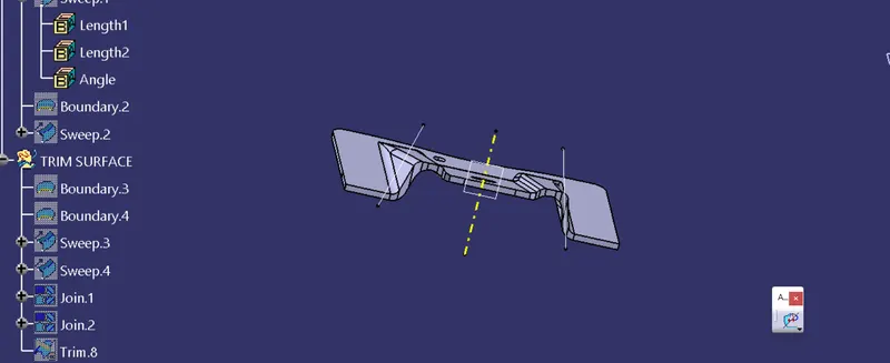
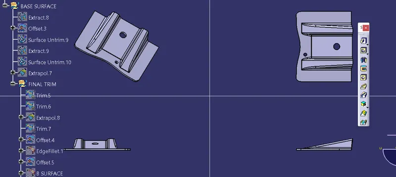
Week 8 - Challenge 1 - Base Bracket Design
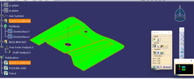
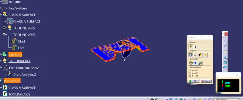
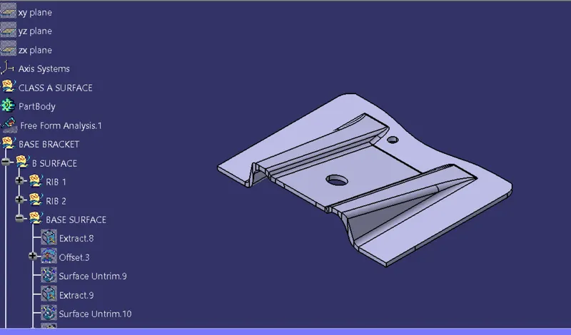
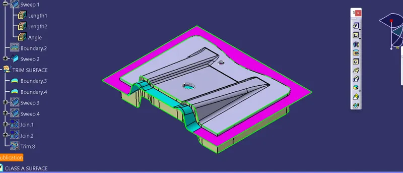
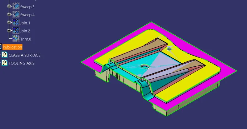
Detail report of draft analysis :
Draft means taper angle of component walls , or faces.
it is used to remove the part easier from the core and cavity or mold.
draft anallysis is one of the method to know the analyze our part model created in CAD is manufacturable based on the draft condition applied.
This is used in all components ,like plastic components, sheetmetal etc.
STEPS :
1. Choose the class A surface.
2. Click the draft analysis tool bar.
3. click on compass and place it on the tooling axis of class A surface .
4.click on the class A surface. it will show draft grafh . the draft anlge should be 3 degree.
5.then it will show the draft of part with green colour.
6. finallly we will get draft analysis of part .
TOOLING AXIS: The direction in which the mold or core and cavity opens for remvoe the mold part from the core and cavity , is called the tooling axis.
TOOLING AXIS CREATION : There are 3 methods in tooling axis.
1. point and direction (X,Y,Z direction method)
2.Normal to surface.
3.Bisecting method.
- First, the given styling surface was imported into CATIA and checked for irregularities by using Join, Boundary and Disassemble option.
- By using the boundary option the boundary of the hole was created and the centre point was marked.
- Then a dummy tooling axis was created with the centre point in the z-direction.
- Then by using zy plane the intersection curves were created as shown below and the same procedure was followed for creating the tooling axis in the Y direction.
- Bisecting lines were used to get the exact medium from the two sides so that maximum positive draft angle can be achieved.
- Finally by using the bisecting line option the tooling axis were created by selecting the tooling axis x direction and y direction axis.
Bisecting method :
In Geometry a Bisecting line that divides the line into two different or equal parts. It is applied to the line segments and angles.
use of those 2 dummy from intersecting sketch create the bisecting line as shown in figure below.