Week 8 - Challenge 2 - Switch Bezel Design
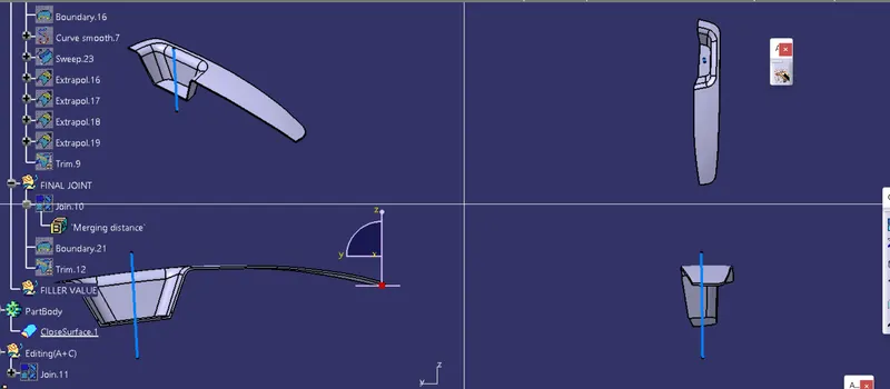
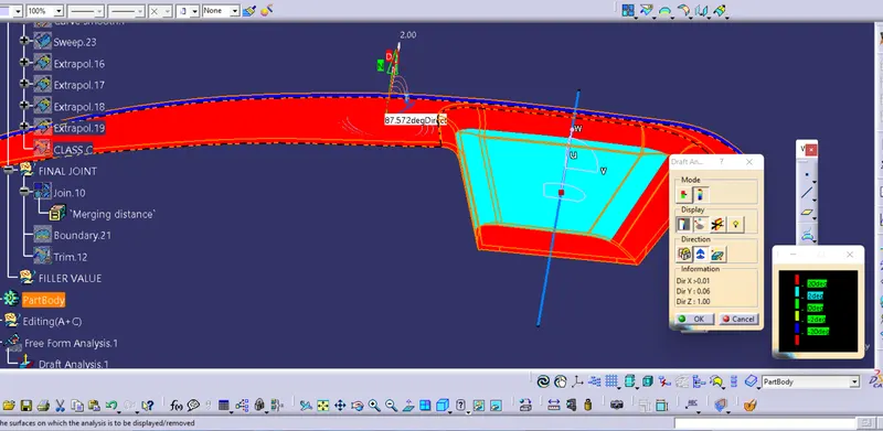
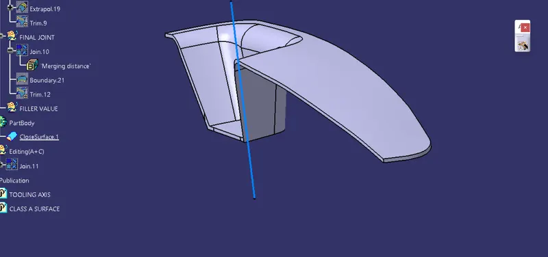
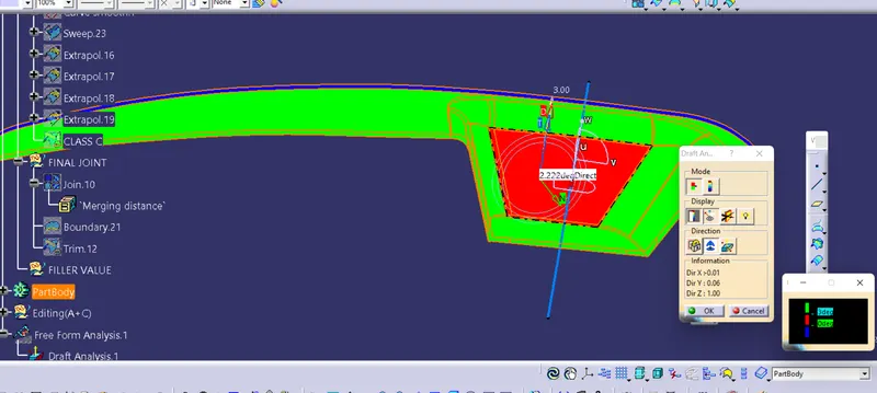
DRAFT ANALYSIS :
The Draft allows the part to easily remove from the mold. The draft angle is to reduce friction between the core, cavity and part and it also avoid the damages. The minimum draft angle is 0.5 degree and the most common draft angle used in the plastic design is 3 degrees.
For plastic parts the Nominal draft angle is 3deg,
First the compass is moved to the part (the compass sholud be placed on the tooling axis) which used to define the new current draft direction, then lock the draft direction using the lock icon
The colour chart indicates the various condition of the draft angle . the green colour indicates that the part passes and the and can be used for the further operations
By using the analysis under the running point icon we can check draft angle at the various surfaces of the component
There are two modes in the Draft analysis quick mode and fully detailed mode
CREAT TOOLING AXIS :
First, the given styling surface was imported into CATIA and checked for irregularities by using Join, Boundary and Disassemble option.
By using the boundary option the boundary of the hole was created and the centre point was marked.
Then a dummy tooling axis was created with the centre point in the z-direction.
First, the given styling surface was imported into CATIA and checked for irregularities by using Join, Boundary and Disassemble option.
By using the boundary option the boundary of the hole was created and the centre point was marked.
Then a dummy tooling axis was created with the centre point in the z-direction.
Then by using zy plane the intersection curves were created as shown below and the same procedure was followed for creating the tooling axis in the Y direction.
Bisecting lines were used to get the exact medium from the two sides so that maximum positive draft angle can be achieved.
Finally by using the bisecting line option the tooling axis were created by selecting the tooling axis x direction and y direction axis.