Attachment Feature Creation
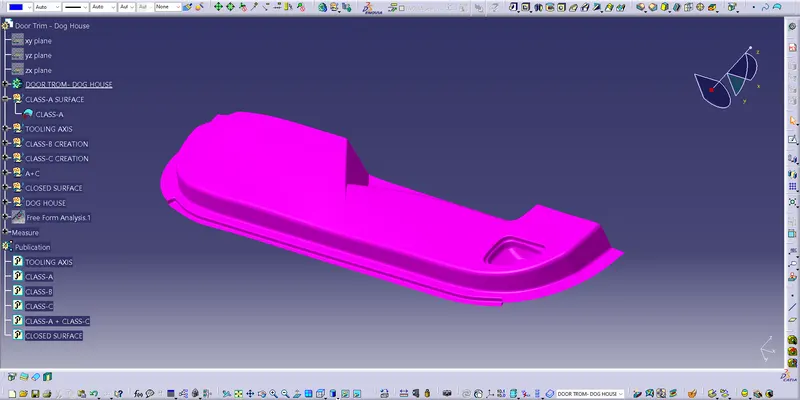
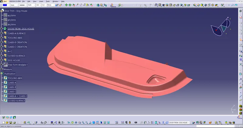
Objective of this Project is to create a Component with the engineering attachment features (Dog House) with considering the Design standards, out of the Given Class-A surface.
|
CLASS-A SURFACE |
|
|
|
CLASS-B SURFACE |
|
|
|
CLASS-C SURFACE |
|
|
|
CLASS-A & C JOIN |
|
|
|
DOG HOUSE |
|
|
|
SOLID PART AND ISOMETRIC |
|
|
|
DRAFT ANALYSIS |
|
|

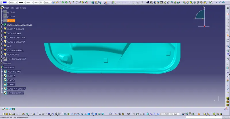
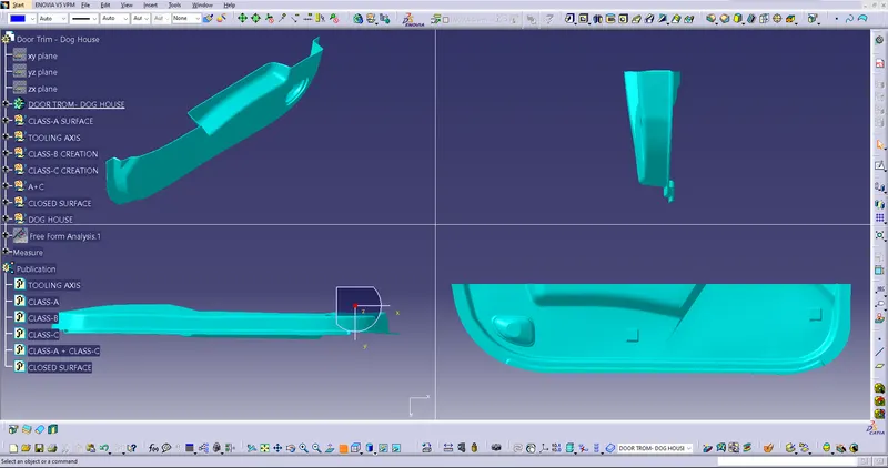
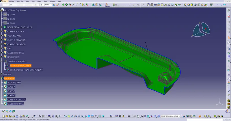
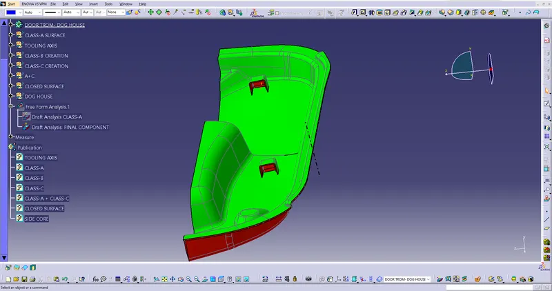
TOOLING AXIS CREATION:
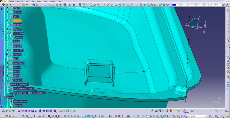
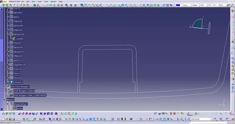
Creating Tooling axis is one of the Important factor of the creation of the component CAD Part. Tooling axis can be created using Bisecting Method by Bisecting two axis clearing the draft angles both in X & Y Direction. Tooling Axis is very important part while designing the CLASS-B. The determination of the direction of Tooling Axis depends on the phases of the surface. In this part a line was created in the Y-Dirction, it cleared the draft analysis of the part, so the line was used as the Tooling Axis. (shown in the picture below). The Bisecting Method of creating the tooling axis is first we create two lines to clear the draft analysis on both components X & Y. When we get both the lines we simply need to bisect it. The line formed by Bisecting those lines will be our Tooling Axis.