Week 9 - Attachment Feature Creation - Challenge 2
- DOGHOUSE DESIGN
- Aim: To create the Dog House for the Door Trim considering the design rules and perform
the draft analysis.
- Objectives:
Create the Tooling axis
Design the class-B and class-C surfaces and join them.
Use the Close Surface feature to make a solid body from the surface.
Design the required dog house and analysis them.
Perform the Draft analysis for the final component.
PROCEDURE:
1. CREATION OF TOOLING AXIS.
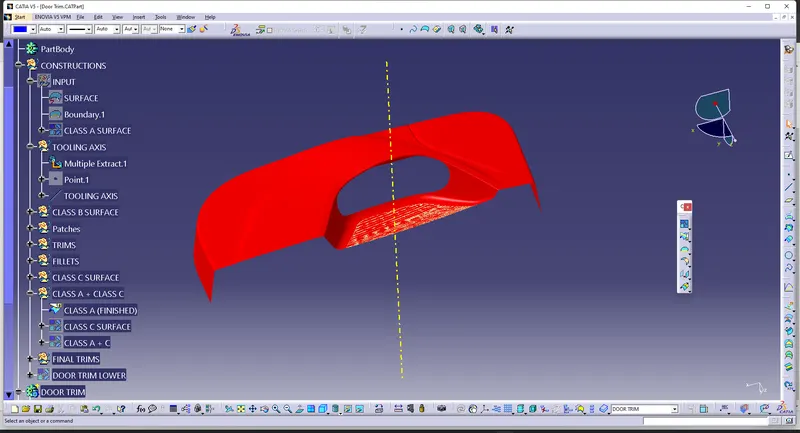
- First, the given styling surface was imported into CATIA and checked for irregularities by using Join, Boundary and Disassemble option.
- Then a tooling axis was created with the centre point generated on surface in the z-direction.
2. CLASS B Creation
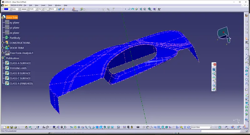
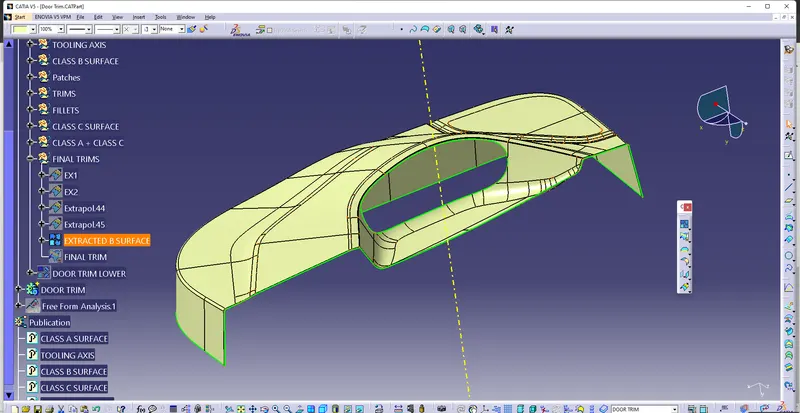
- By offsetting the Class A surface at 2.5mm distance (Because component thickness is 3mm).
- Somewhere surface section are break by offset the surface
- where, sections are broke are reconstruct by using Extract, Untrim and Extrapolate features
- then Combine those section to the Offset surface.
- After the Class B surface as Created
CLASS B
EXTRAPOLATED CLASS B
3. CLASS C Creation
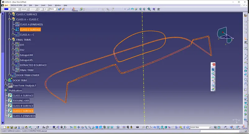
- From the Class A surfaces using Boundary command to all edges of the surface
- then sweep those section by define by reference surface with guiding of boundaries
- sweep at the angle of 90 degree at distance of 4mm
- after that join all Sweep section of the surface and considered as Class C surfaces.
4. FINAL Bumper Creation
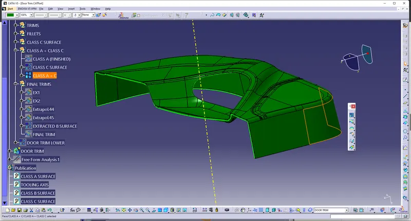
- Join Class A and Class C surfaces
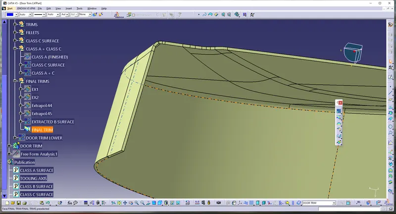
- Then Trim Class B and Join of (Class A and C surfaces).
CLASS A + CLASS C
FINAL TRIM ( CLASS(A+C) - CLASS B)
5. CREATION OF CLOSED BODY
- Go to the part design and close the feature.
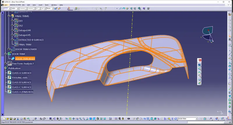
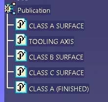
- TREE STRUCTURE
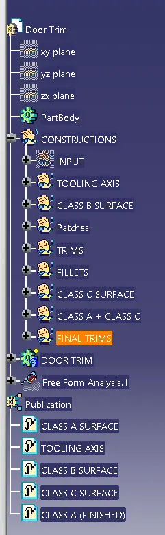
- PUBLICATION
5. DRAFT ANALYSIS
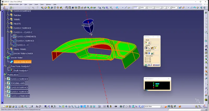
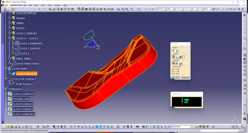
- For plastic parts, the nominal angle value for draft analysis is 3 degree but even a 0.5-degree angle can be created for sub-assemblies like ribs and slots. (For Sheet Metal 7 degree angle is the nominal value)
- Insert – Analysis – Feature Draft Analysis
- Draft analysis was carried out by pulling the compass to the tooling axis and an inverse draft axis was carried out if required.
- After setting the compass over the tooling axis the compass must be locked to a specific direction.
6. DOG HOUSE DESIGN:
Dog house: Dog house is an engineering feature used in the plastic trim design. Dog
houses are used as supporting features. Sometimes other engineering features like
snaps; locators, etc. are mounded on them to increase their strength. Dog house and
other engineering Features are built on B-surface.
Design rules for Dog house creation
"C" is where the doghouse contacts the backside of the surface
Doghouse wall thickness at the intersection of the part wall ( C ) should be 40% or less
than the main wall stock ( T ).
The height of ( B ) should be between 3.0 – 6.0 mm
Dog house design procedure by considering the design rules:
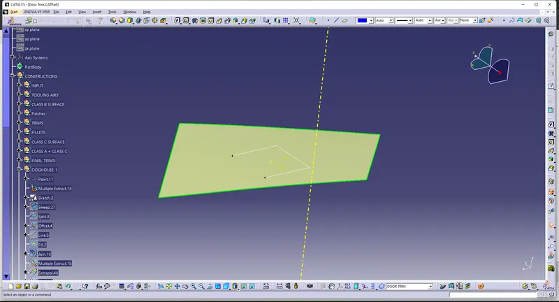
Extract the surface on which we want to create the dog house and create a sketch on a
plane
STEPS:
1.Doghouse sketching using sketcher workbench with proper Iso constraining factor.
2.Now we have closed the upper surface of the dog house by extruding and trimming
features.
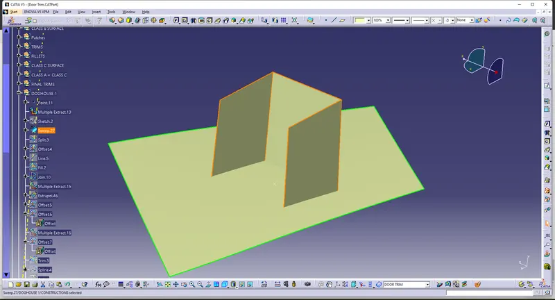
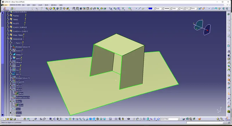
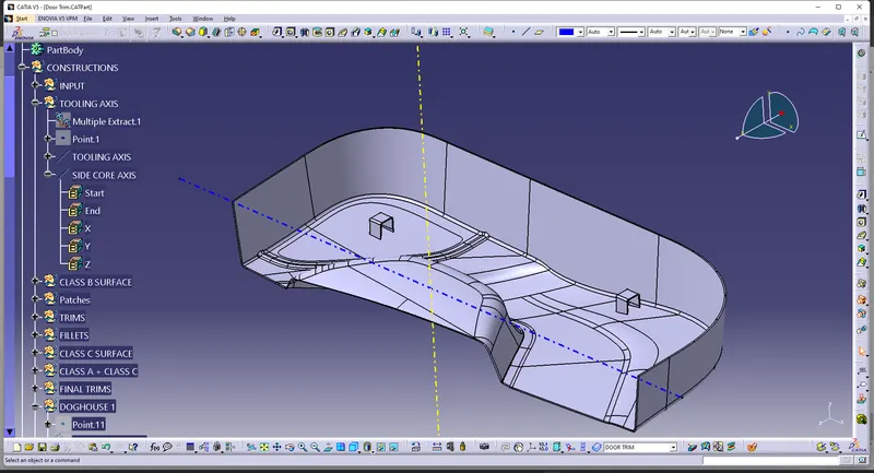
Side core tooling axis creation:
side core axis is created in the x direction on the same point as the main tooling
direction created
2mm thickness has given to the surface by using a thick surface feature
Now apply the fillet value to the side wall and outer edges
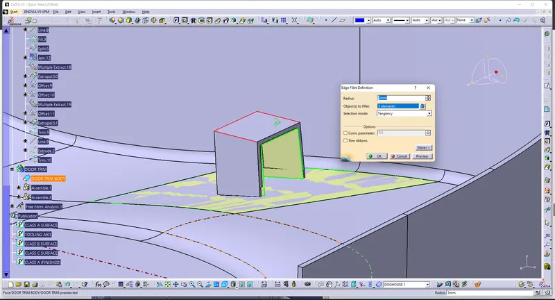
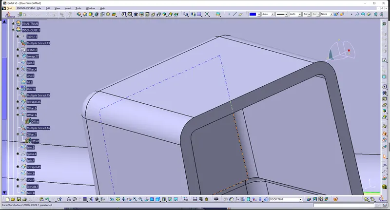
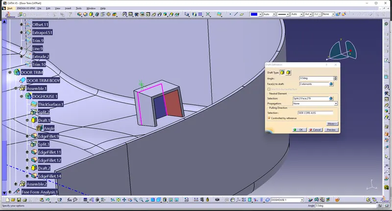
Give the draft angle to the inside walls and pull direction as the side core axis
The height of ( B ) should be between 3.0 – 6.0 mm by considering the design rule
here we offset the class b surface to 6mm
Doghouse wall thickness at the intersection of the part wall ( C ) should be 40% or less
than the main wall stock ( T ).
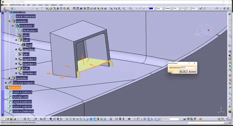
we offset the 1mm from the side wall by considering the design rule
Now we trimmed the surfaces and split the surface with the part body
Now apply the draft on the inside edge where the bottom cut is done
Apply the fillet to those edges
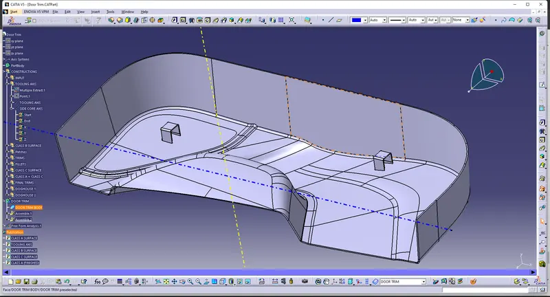
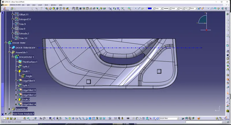
finally, The dog house is created by considering the design rules.
Following the same procedure, we designed another dog house on the door trim in the
required position
Draft Analysis on the final component :
1. The part created has to be changed to the material mode in the display frame.
2. Compass is enabled and aligns it along with the tooling direction.
3. The lock command is then applied to fix the compass along with the tooling axis.
4. Color codes are classified and Draft angle is applied.
5. Running point analysis is used to display permissible draft angles.
Draft analysis on the dog house considering the side core axis as our tooling direction.
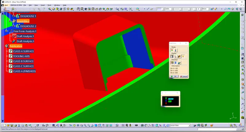
Draft analysis of final component considering the main tooling axis as the tooling
direction
Conclusion :
Hence, the dog house for the door trim was created by considering the design rules, and
the Draft analysis performed on the final component is successfully done.
NOTE: FOR ATTACHMENT FEATURE CREATION (DOGHOUSE) , USED THE SAME DOOR TRIM LOWER PART.