Week 8 - Challenge 4 - Bumper
AIM : To create the Bumper Plastic component through the given Class-A surface.
OBJECTIVE : The objective is to create the Bumper Plastic component through the given Class-A surface. To begin with, the tooling axis for the given Class-A Surface should be created meeting the requirements of the draft angle and at the end perform the Draft analysis on the model.
STEPS:
1. CREATION OF TOOLING AXIS.
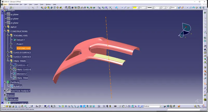
- First, the given styling surface was imported into CATIA and checked for irregularities by using Join, Boundary and Disassemble option.
- Then a tooling axis was created with the centre point generated on surface in the z-direction.
2. CLASS B Creation
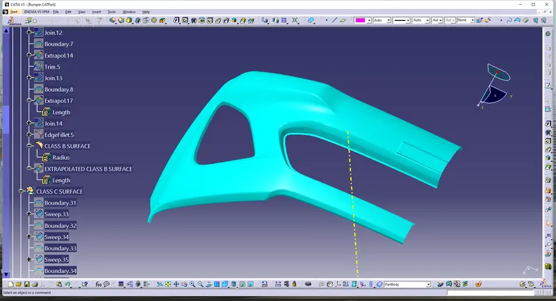
- By offsetting the Class A surface at 3mm distance (Because component thickness is 3mm).
- Somewhere surface section are break by offset the surface
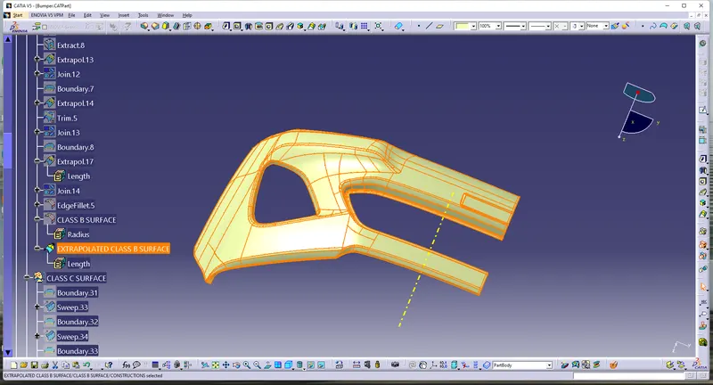
- where, sections are broke are reconstruct by using Extract, Untrim and Extrapolate features
- then Combine those section to the Offset surface.
- After the Class B surface as Created
CLASS B
EXTRAPOLATED CLASS B
3. CLASS C Creation
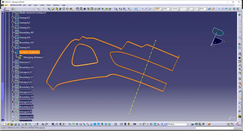
- From the Class A surfaces using Boundary command to all edges of the surface
- then sweep those section by define by reference surface with guiding of boundaries
- sweep at the angle of 90 degree at distance of 5mm
- after that join all Sweep section of the surface and considered as Class C surfaces.
4. FINAL Bumper Creation
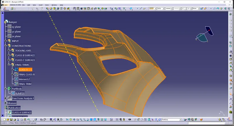
- Join Class A and Class C surfaces
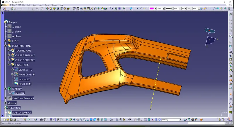
- Then Trim Class B and Join of (Class A and C surfaces).
CLASS A + CLASS C
FINAL TRIM ( CLASS(A+C) - CLASS B)
5. CREATION OF CLOSED BODY
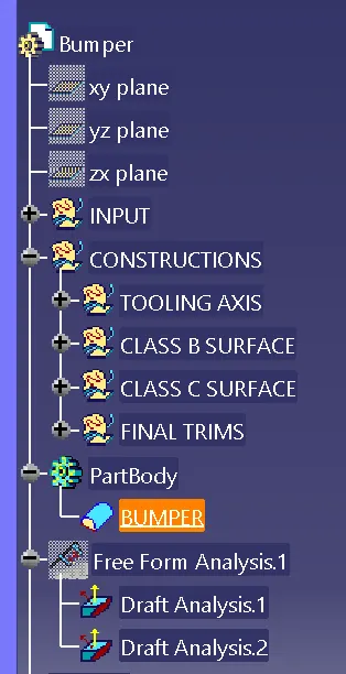
- Go to the part design and close the feature.

- TREE STRUCTURE
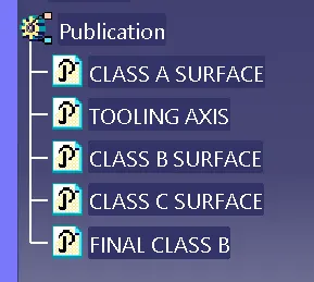
- PUBLICATION
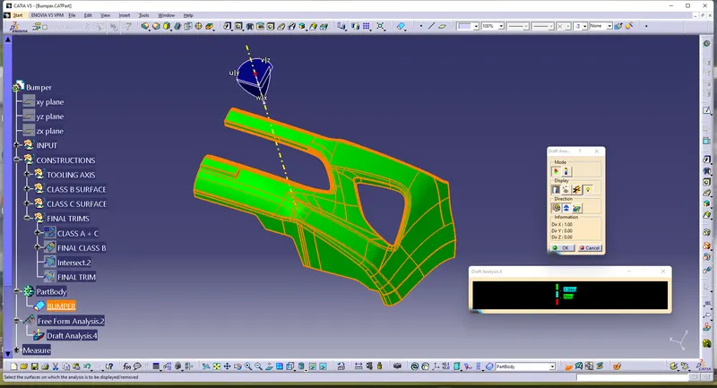
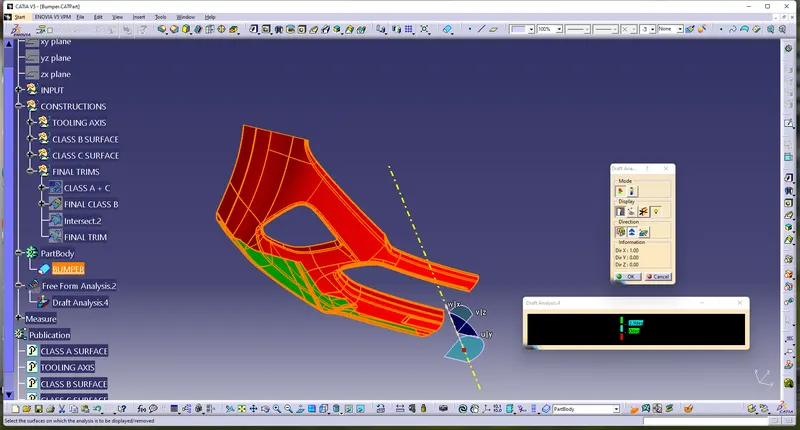
5. DRAFT ANALYSIS
- For plastic parts, the nominal angle value for draft analysis is 3 degree but even a 0.5-degree angle can be created for sub-assemblies like ribs and slots. (For Sheet Metal 7 degree angle is the nominal value)
- Insert – Analysis – Feature Draft Analysis
- Draft analysis was carried out by pulling the compass to the tooling axis and an inverse draft axis was carried out if required.
- After setting the compass over the tooling axis the compass must be locked to a specific direction.
CONCLUSION :
Thus the draft analysis for fan cover was carried out by creating the perfect tooling direction and the given class-A surface was ready to move on for further operations.