Week 9 - Attachment Feature Creation - Challenge 2
DOOR TRIM
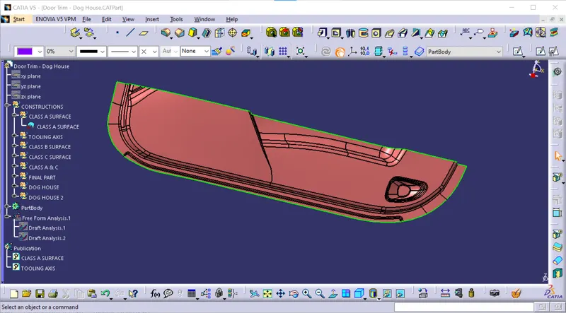
class A surface
the above figure shows that the class A surface .
Creation of tooling axis
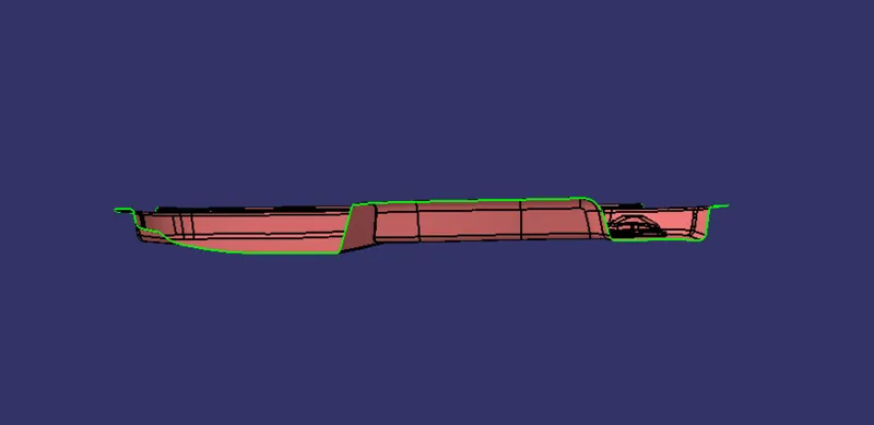
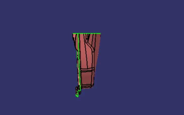
for creation of tooling axis we need to see the part in all the views from that we need to get that which view (front view, side view, top view) clears the maximum flat faces.
Front view
side view
Top view
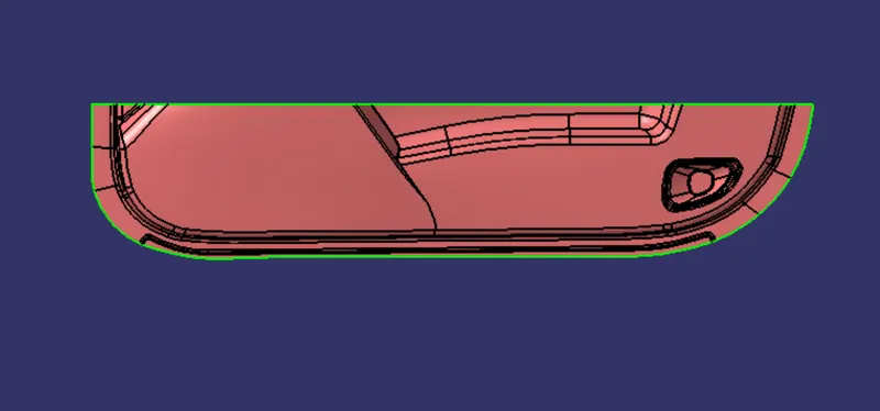
after observing the class a surface in all the views as shown in the figure that we know that the top view clears the maximum flat faces as shown in the figures above.
for that we need to create th extract at the flat face as shown in the below figure after that we need to place a point on the middle of the surface then we need create the line which is normal to the extract that we have created as shown in the figure below hence the tooling axis is created as shown in the below figure
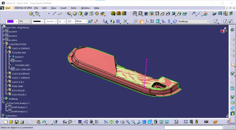
after creating of tooling axis then we need to do the draft analysis on the given class A surface for identifying the draftangle of the given class A surface
Draft analysis of class A surface
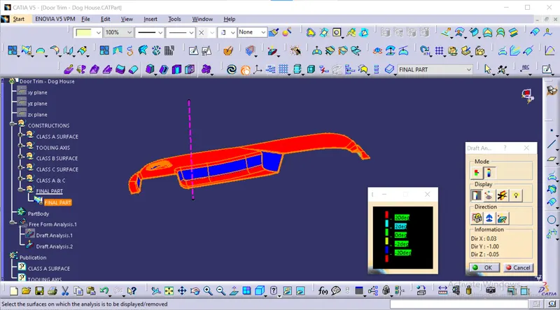
The above figure shows that the draft anlysis on the class A surface which is used to know the draft angle of the given class A surface for that we need to use the draft anlaysis of the given class A surface as shown in the above figure.
after completion of the draft analysis on the given class A surface then we need to create the class B surface for the given class A surface by using various commands of catia v5 generative shape design as shown in below figure
Class B surface
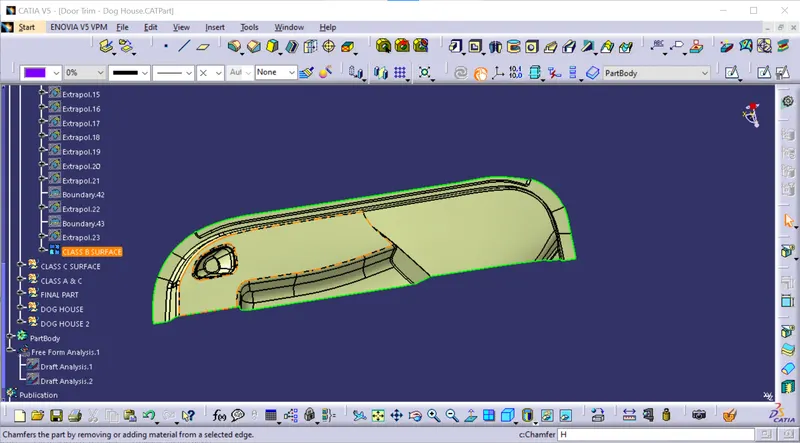
the above figure shows that the class B surface
Class C surface
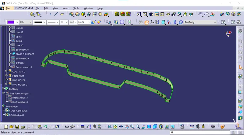
the above figure shows that the class c surface that is created by using the sweep command
Class A & C
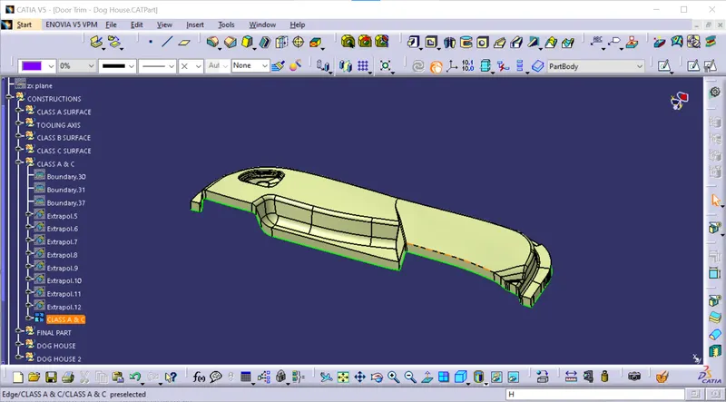
the above figure shows that the combination of class A and class C surface by using join command and also with a high precision value of 0.001 .
Final part
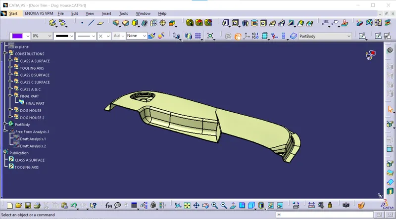
the above figure shows that the combiination of the class A and C surface with the class B surface by using the trim command to form the final part
Close boundary conformation on final part
after completion of the final part we need to check weather there s no open boundaries in the final part by using the boundary command as shown in the below figure
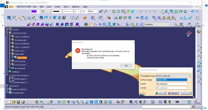
after ensuring that there is no open boundaries in the final part then we need to proceed to the close surface command .
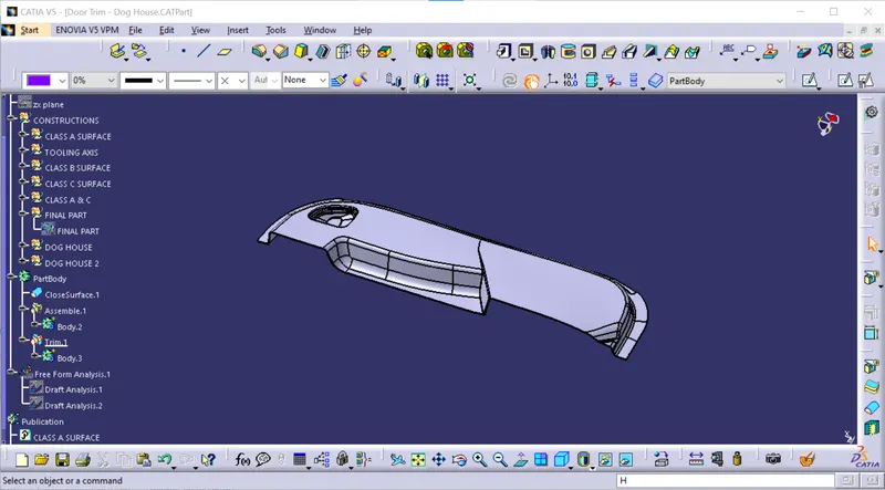
Close surface
for that we need to the define the part body after that we need to go to the part body then we need to select the close surface commmand after that we need to click on the part then ok after that the close surface is formed as shown in the below figure.
Draft analysis on the final part.
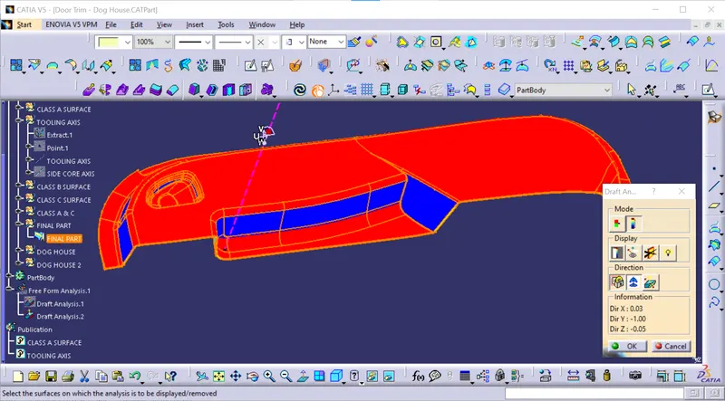
after completion of the final part we need to do the draft anlysis on the final part for that we need to change the part apperance into material mode after that we need to go to the analysis tab on that there is a option called draft anlysis . after selection of the draft analysis command then need to click on the axis system command in the draft analysis after that we need to drag the axis system and place it on the tooling axis then we need to lock the movement of the axis system by using the lock option after locking the movement of the axis system then we need to click on the part after that the colour of the part changes according to the criteria in the draft analysis window . the criteria shows that the draft angle is seperated by different colours as shown in the above figure . after that we need to click on the ok option then the draft analysis is completed as shown in the above figure from the drat anlysis command we need to know that the draft angle of the given part .draft angle is very important for the part due to thedraft angle we can reduce the scrap and alos we get the accuracy while the part is removing from the core and cavity if there is no draft angle present in the part it increses the friction between the cavity and the part and also it completely damages the part and it increses the scrap also thats why we need to provide the draft angle for the part.drat angle of the part increases the quaity and also the accuracy of the part also draft angle for the part is compulsary to get precision and also good finish and also it saves the part from the damages which are from the coore and cavity for that we need to do the draft analysis on the final part.
Dog house
for the creation of the dog house we need to follow some design rules as shown in the below figure for the perfect design of the dog house
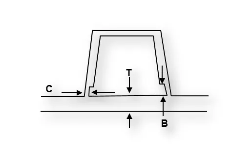
design rules for dog house
-
Doghouse wall thickness at the intersection of the part wall ( C ) should be 40% or less than the main wall stock ( T ).
-
The height of ( B ) should be between 3.0 – 6.0 mm
dog houses are used for if there is a screw bose which is needed at 20mm from the class B surface it is much more complicated to manufacture or to design a screw bose that much long to solve this issue we need to use the dog house insted of making a screw bose that much long by using the dog house solve the issues that we are discussed before .
from the above rules we need to make the dog house properly as shown in the below figure
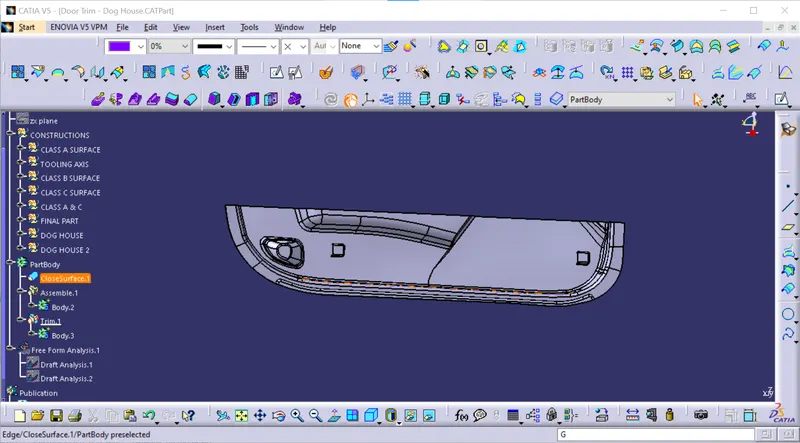
by using the design rules we made the dog house as shown in the above figure
Tree structure
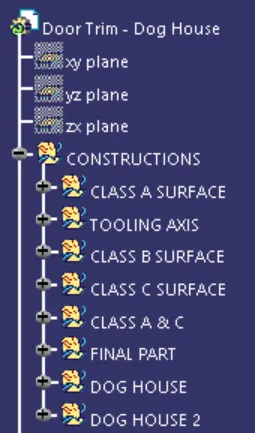
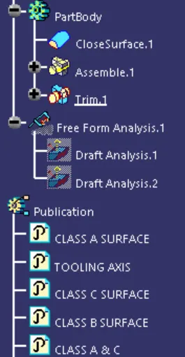
we need to maintain proper tree structure and also it is easily understandable to others who are working in the same project