Week 9 - Attachment Feature Creation - Challenge 1
AIM:
Create the rib for the Centre console coin holder considering the design rules.
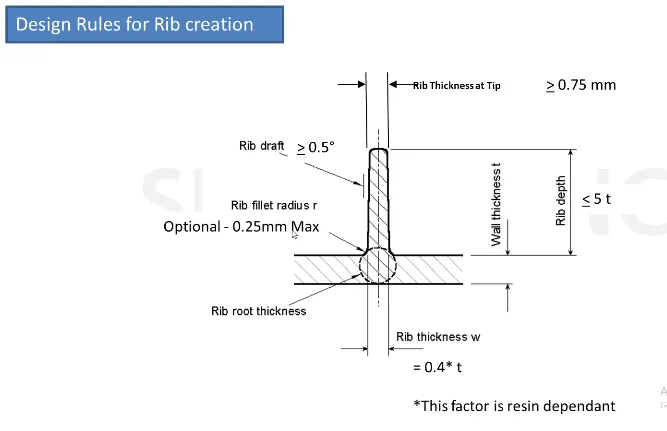
Design Rules for rib creation.
Sketches:
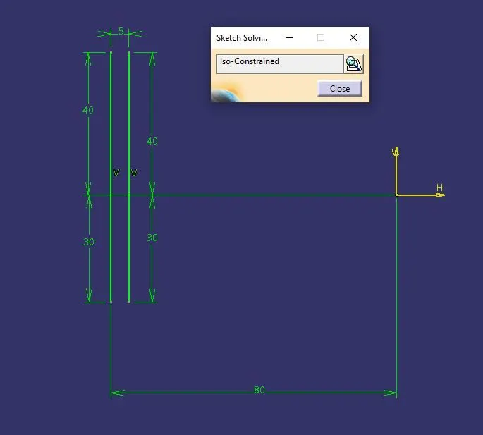
This is sketches for the ribs which are iso-constrained.
Tree Structure :
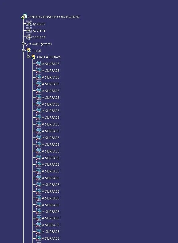
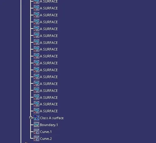
Inputs:
construction:
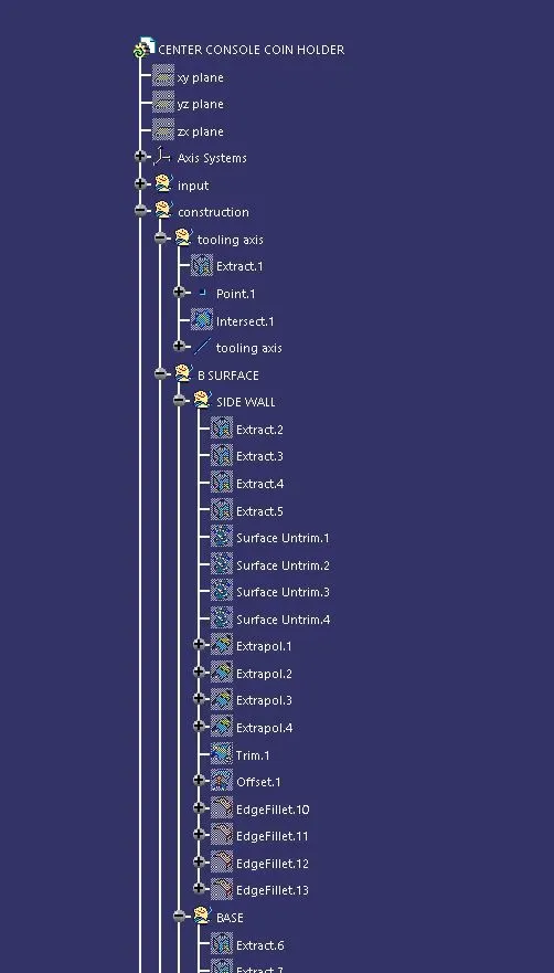
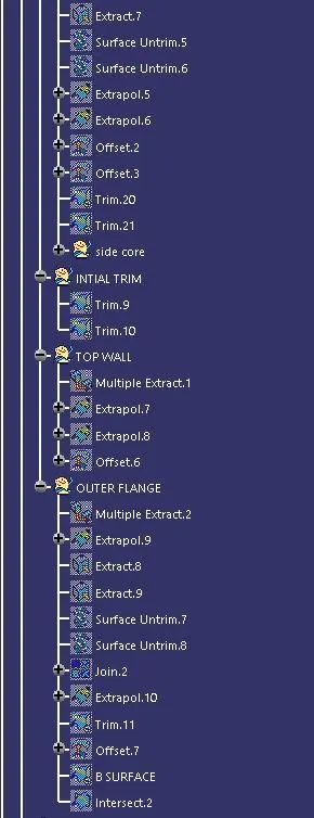
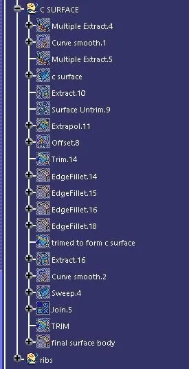
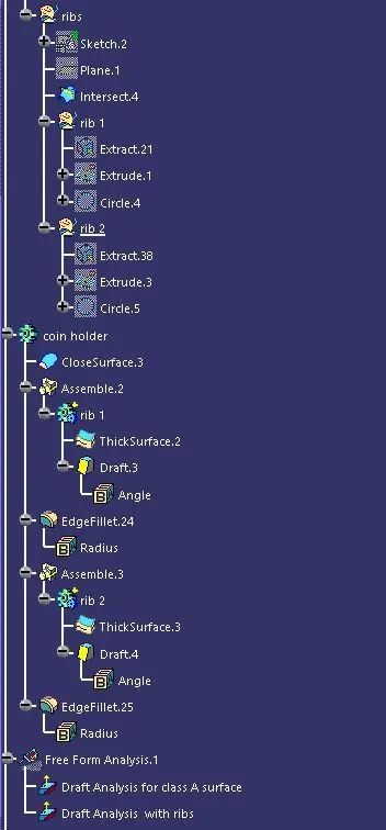
Tree Structure for ribs :
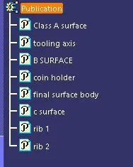
publication:
Tooling axis creation:
To create the tooling axis the we require line which is perpendicular to the class A surface . for that line we required point, which is extracted from the base surface of class A surface.
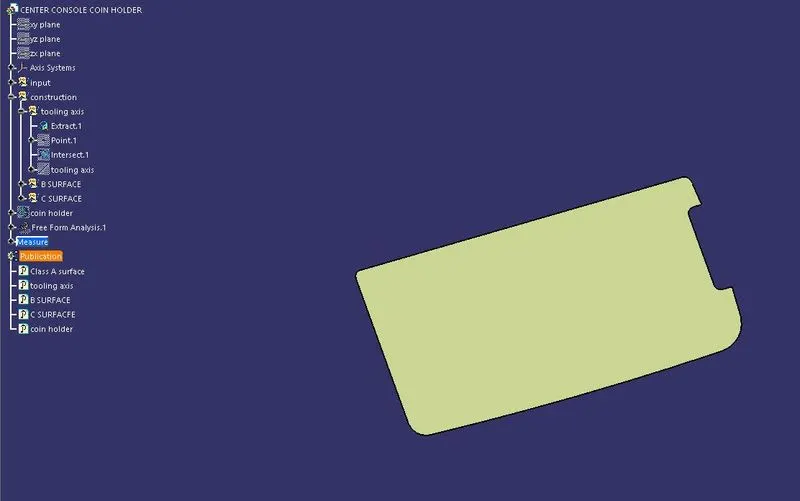
After extraction of the base the point is created on the surface using point on surface.(In point definition dialog box)
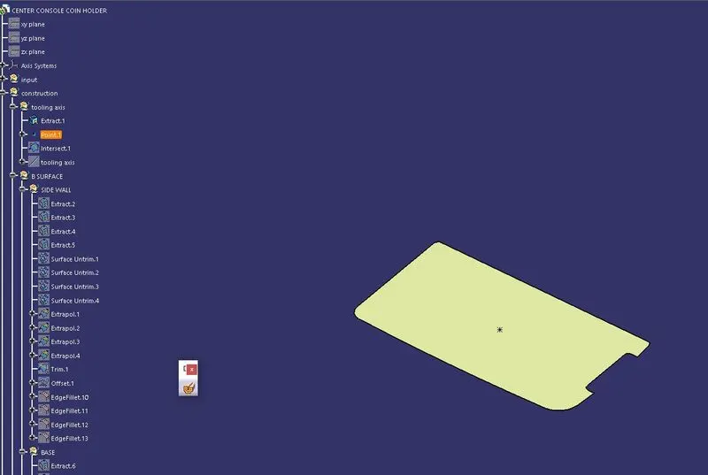
from line definition dialog box line is drawn using point-direction option.
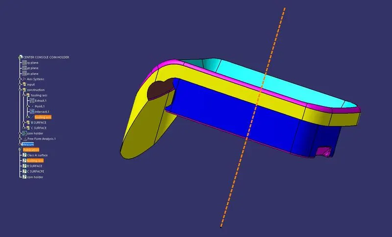
this tooling axis is created from the intersection between the yz plane and class A surface.that axis is then published using publication.
Design of ribs for the coin holder following the design rules :
- creating geomentric set for ribs
- sketching the ribs line using Positioned sketch
- check whether sketch is iso- constrained.
For creating ribs base of the surface is extracted.
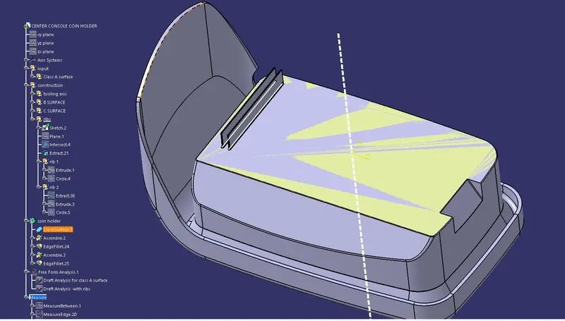
After extracting the base surface. the rib lines are separately extracted and inserted into the geomentric sets rib 1 amd rib 2.
- The extracted line from the sketch 2 (rib1-line) is extruded along the direction if the tooling axis.
- the height of the rib should be 5 times the wall thickness.which is (5*t)
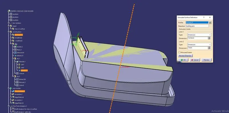
- In this the thickness of the surface body is 2.5 . so (5*t) 5 times the thickness,which is 12.5(5*2.5).
After the dimension is given to the extrude.workbench is changed from generative shape design to part design.For draft and thick surface a separate body is provided. Which is named as rib 1 and rib 2.
which is then assembled to the coin holder part body.
- In the part design the extruded surface is added with thickness using thick surface option.
- thickness of the rib according to the design rules are considered as 40% of the wall thickness.
- In this part the wall thickness is 2.5(40% of 2.5 is 1mm) so rib is 1mm.
- Rib with thickness is then drafted using draft with the angle of 0.5 deg is provided in design rules of the rib creation.
same process is carried out for rib 2. the space between the ribs are calculated using design rules which is (2*t).after creating the ribs the edgefillets are given to the both ribs.
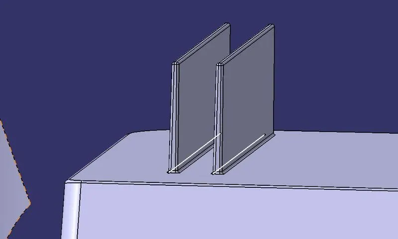
Now, the ribs are formed. Rib root thickness analysis from design rules are taken into consideration.
Rib root thickness analysis :
To do the analysis intersection is taken between plane 1 and surface body.
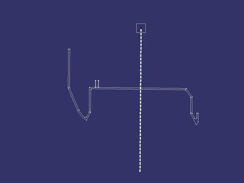
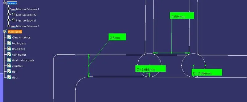
intersection path consists of both ribs and bodies intersection along the plane 1.which is shown in the above image.
to measure the rib root thickness the from the ribs
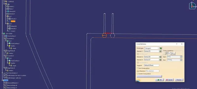
for creating the circle in the rib root ,three elements are extracted and joined to form tritangent circle.
element 1 and 2 are the ribs base fillet.the intersection of the class a surface is the third element for the tritangent circle.
Now the circle is created the diameter is measure and the required value is checked for rib root thickness.
same process is reapeated for rib 2. to find out the rib root thickness.
Draft analysis for the ribs:
The drafting feature is present in insert option. after applying the draft angles with tooling axis in mode option.click on the body to check the drafting colours
green which is above O.5 deg
red which is 0 deg
blue which is below 0 deg.
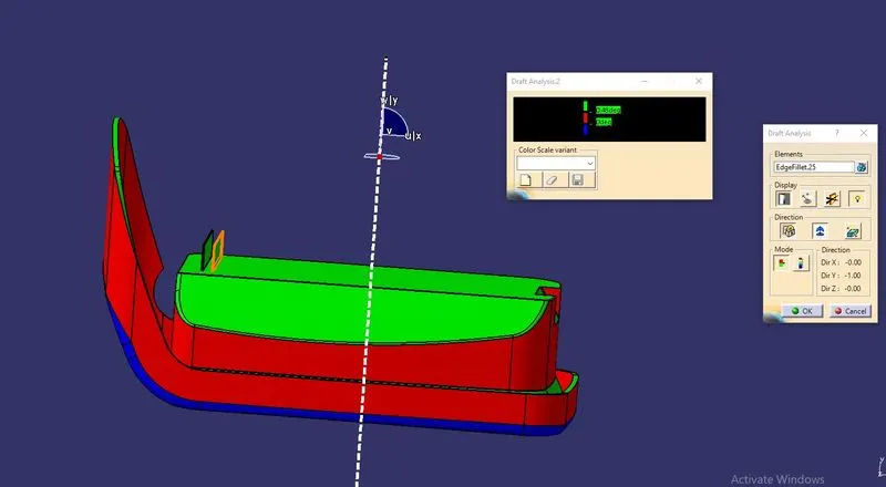
The drafting angle is 0.5 deg for ribs because the design for rib should only be more than equal to 0.5 deg according to the design rules.
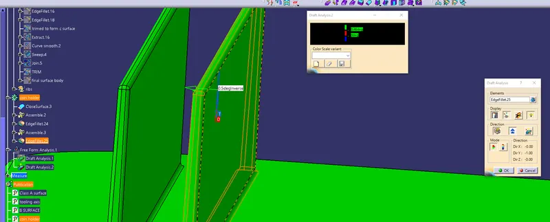
so the draft analysis is done 0.5 deg on ribs . according to the design rulers
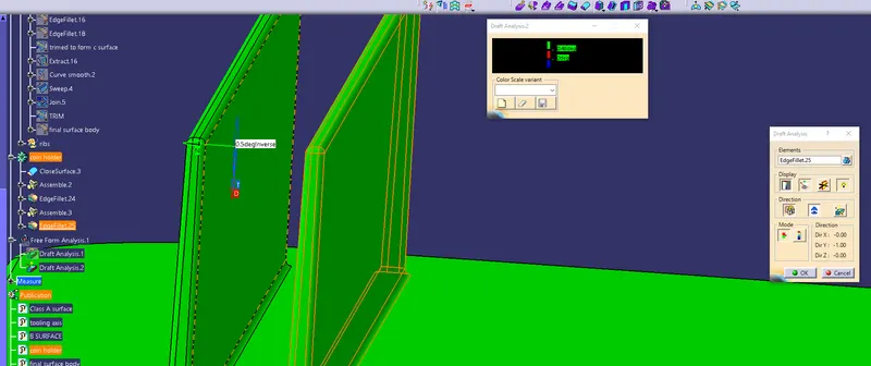
draft analysis done on the both the ribs
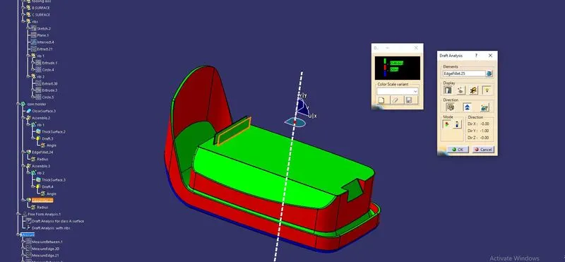
red color areas are displayed because the tooling axis is parallel to the part.
draft analysis on class a surface:
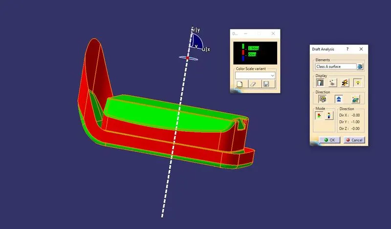
The drafting feature is present in insert option. after applying the draft angles with tooling axis in mode option.click on the body to check the drafting colours
green which is above 3 deg
red which is 0 deg
blue which is below 0 deg.
red color areas are displayed because the tooling axis is parallel to the part.
conculsion:
ribs are created with proper tooling axis and draft analysis using design rules.rib root analysis is done on the base of the rib root to determine the required value according to the design rulers.