Week 9 - Attachment Feature Creation - Challenge 1
Design of Ribs
Ribs are indispensable functional structures on many plastic parts. It can effectively improve the rigidity and strength of plastic parts like the H beam. By using ribs, it is not necessary to greatly increase the wall thickness of the plastic parts, and ribs are not undercut structures like the H beam whose structure will be difficult to make for plastic injection molding. So ribs work well for plastic parts that are subject to pressure, torsion, and bending. Ribs can also act as internal flow passages to aid in the plastic melt filling flow, which is of great help to the formation of complex and large plastic parts.
Ribs are generally designed on the non-appearing surface of the plastic part, and its direction is as close as possible to the flow direction of plastic melt filling. Ribs should neither be too long nor too thick, otherwise, it will increase the difficulty of injection molding, causing problems such as voids and sink marks on the back.
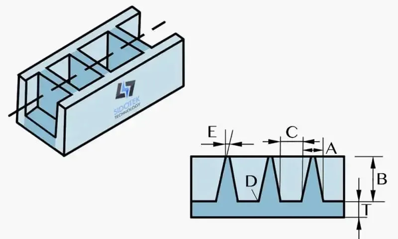
Rules for thermoplastic ribs
- T: Nominal wall thickness
- A: Base width of a rib: 0.3-0.7T
- B: Rib height: less than 3T
- C: Spacing between ribs: more than 4T
- D: Radius at base of rib: T/8
- E: Draft of rib: 0.5°-2°
Rules for thermosetting plastics
- A: Base width of the rib
- B: Top width of rib: 0.5T
- C: Rib height: 3T
- D: Radius at top of rib: T/4
- E: Radius at base of rib: T/4
- F: Draft of rib: 5°
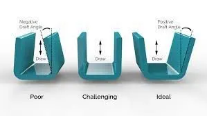
Draft Angle - A draft angle is a taper applied to the vertical walls of the injection-molded component to assist with releasing the part from the mold. A draft angle allows you to use a simple push on the ejector pins to pop your part out of the mold. This way, you will prevent the part’s surfaces from being dragged along the mold when ejected. Friction between your part’s surface and the mold’s surface can cause scratches and affect your part’s appearance.
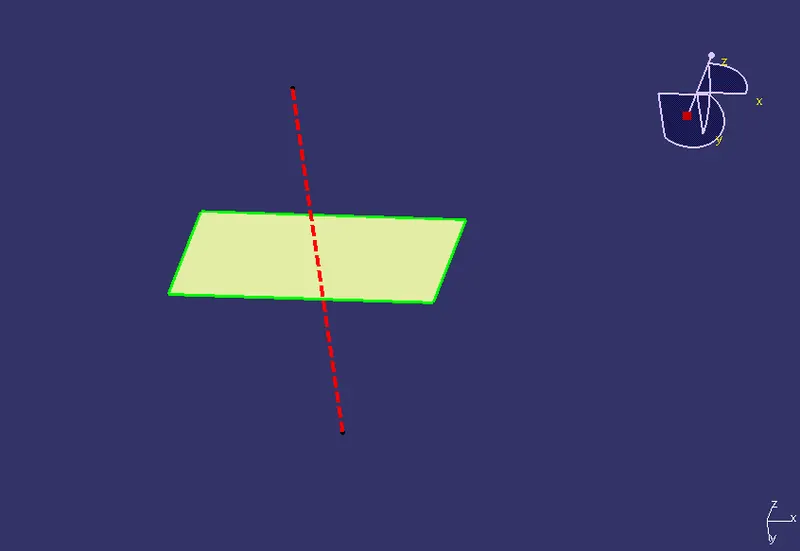
Creating Tooling Axis
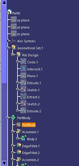
Step 1. Extract Base of the coin holder.
Step 2. Untrim it.
Step 3. Create a point on the surface
Step 4. Create line in the Y axis on the point.
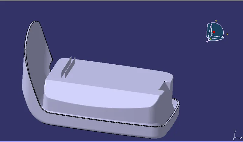
Creating Rib
Step 1 Create a sketch on the base of CH.
Step 2. Draw a line and constrain it.
Step 3. Extrude it along the tooling axis. Make sure the height is 5 times the thickness of the component.
Step 4 Open part file and insert body then thicken the rib by giving 1mm thickness.
Step 5 Assemble the rib with the main part body.
Step 6: Set the Draft angle to each face as 0.5 degrees and give a fillet value of 0.25.
Step 7. Similarly repeat the process for the other rib and make sure that the distance between the two ribs should be the ratio of height by width should be less than 3.
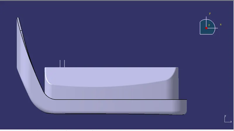
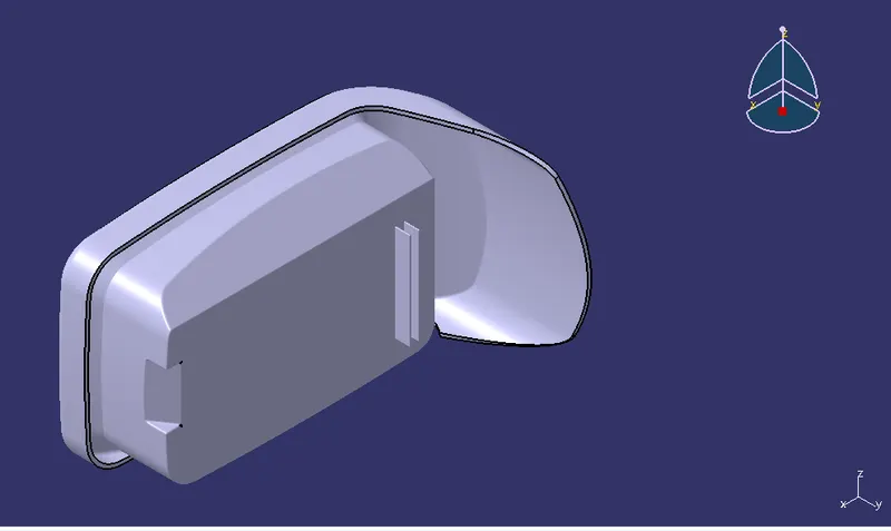
Design Rules followed in this project
- Nominal wall thickness of plastic component 3mm, where deviation of +-30% is accepted. I,e 2.1 to 3.9. We have taken thickness of 2.5 mm.
- Ideal draft for component is 3 deg and 0.5 for rib.
- Radius of fillet for ribs should be 0.125 * t (t is thickness).
- Thickness of ribs should be 0.5 * t.
- Distance between two ribs should be atleast 2*t.
- Minimum thickness at tip of rib should be .75 mm
- Height of rib should be 5*t.
- Height to width ratio should be 3:1 for steel while 2:1 is preferred.
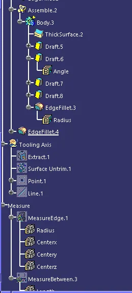
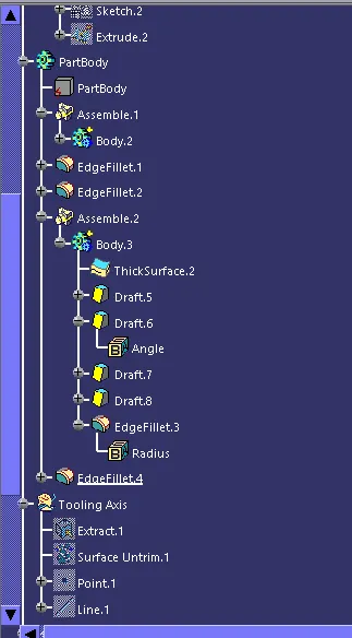
Tree Structure