Week 8 - Challenge 2 - Base Bracket Design
Draft Analysis on a Base Bracket
To create the tooling axis for the given Base Bracket model meeting requirements of the draft angle and performing the draft analysis on the model meetings the requirements of the draft angle and performing the draft analysis on the model.
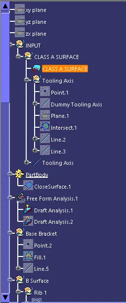
Objective: Ensure Proper Tree Structure
- Geometrical sets should have a proper name based on the sketches present inside of it
- All the sketches should be created under the Geometrical set
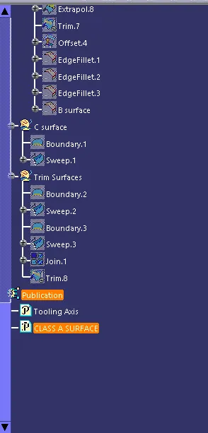
- Publications: Use the publication option and publish the below
- Tooling Axis
- Class A surface
Procedure
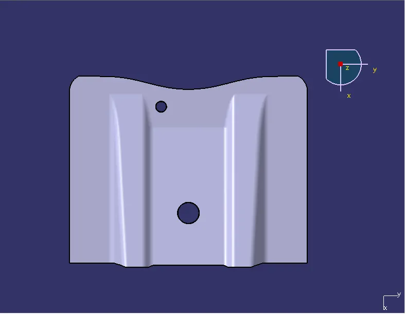
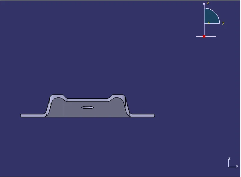
Step 1. Step1. Import the class A surface model.
Step 2 Create a dummy tooling axis by creating a point on a bigger hole. YELLOW DOTTED LINE.
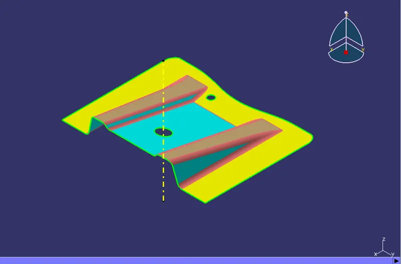
STEP 3 Creating intersection lines with reference to yz plane.
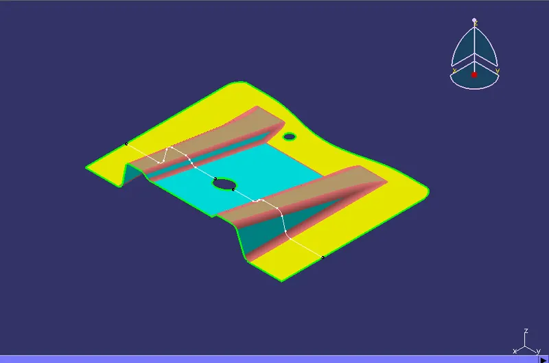
Step 4: Creating bisecting line with reference of two lines, which gives us the tooling axis.

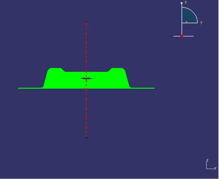
Step 5. We got the tooling axis in a red dotted line.
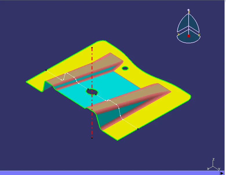
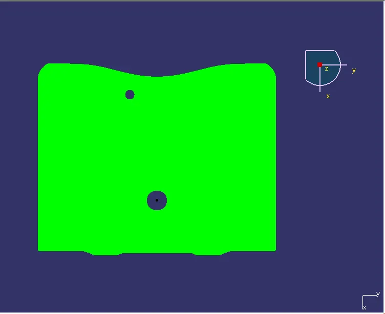
Step 6. Now publish the tooling axis and class-A surface and run draft analysis.
The draft angle for the green zone is 3 deg. The compass is aligned and locked with the tooling axis in the Z direction.
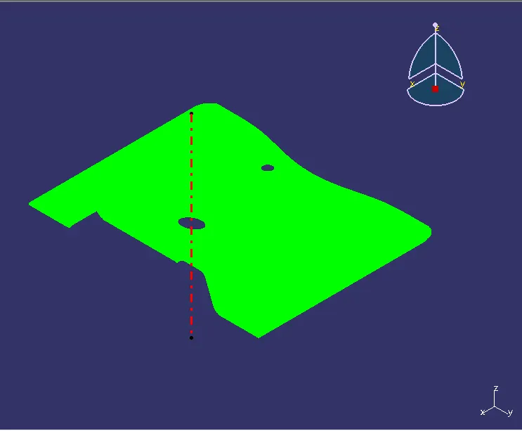
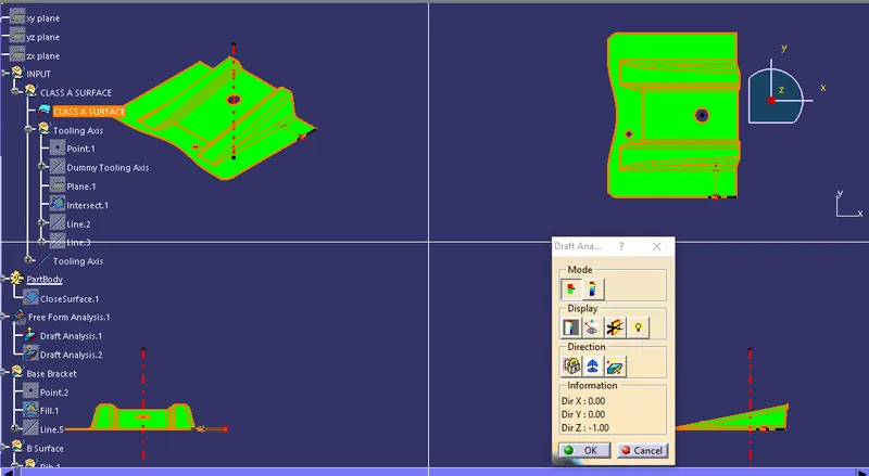
Designing of Class B and Class C surface from input Class A surface.
Class A surface is the input surface that is aesthetically designed by styling.
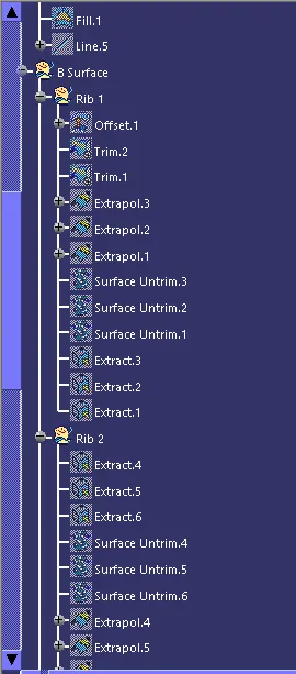
Class B surface is the supporting surface which is an offset of class A and different engineering features are created on it.
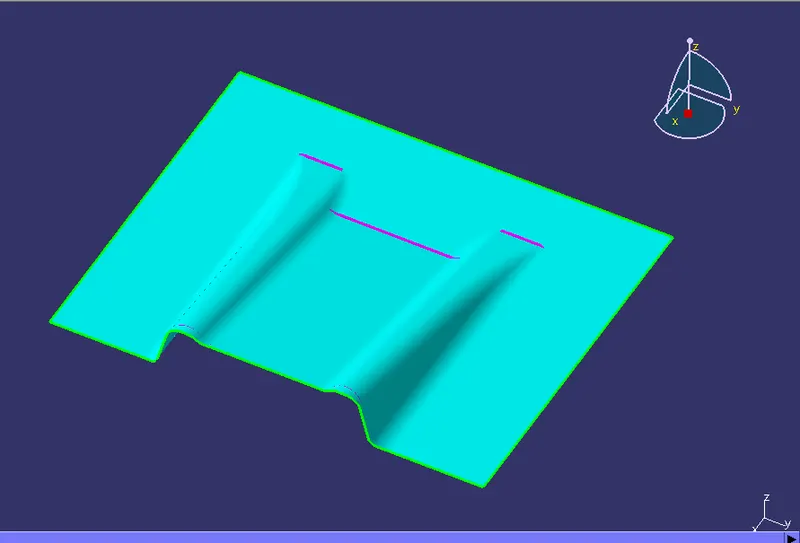
Class C surface is which connects Class A and Class B to form a closed surface with no boundaries and solid can be formed out of it.
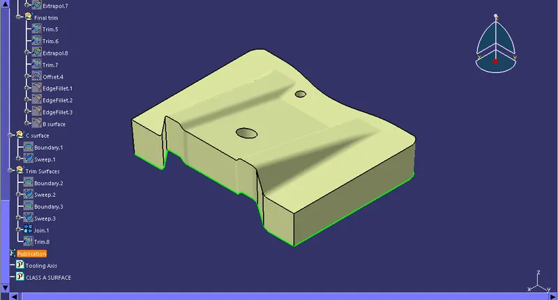
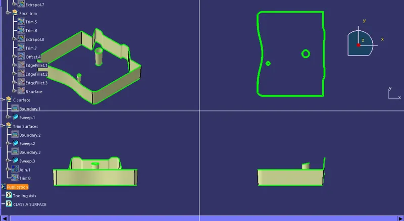
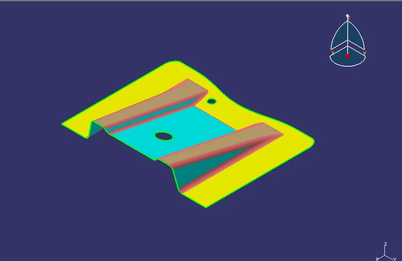
Trimming Class B and Class c surface gives us the final output.
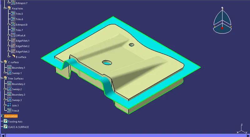
We got the final output with no boundaries.
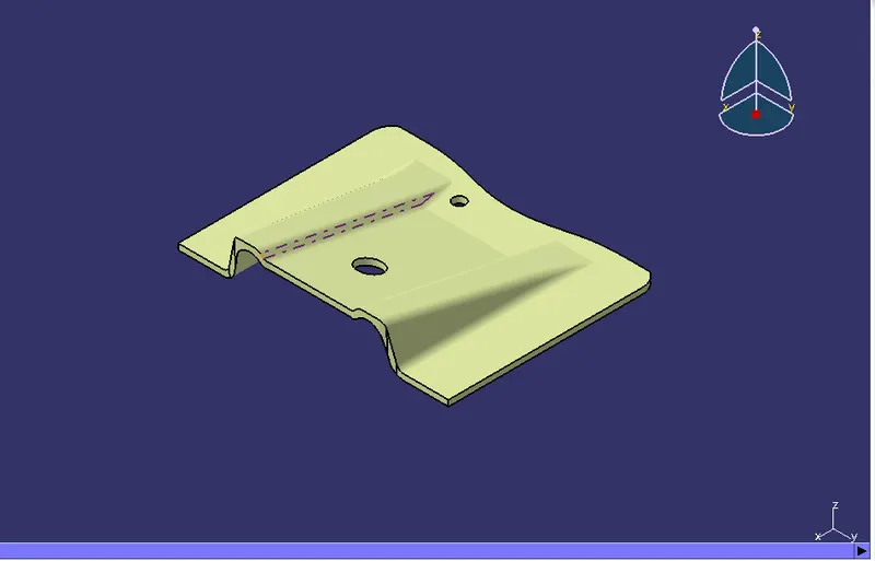
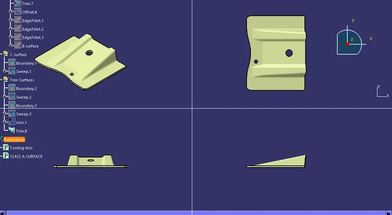
We will create a solid model by going into the part file and selecting the close surface option. This will give us a solid body.
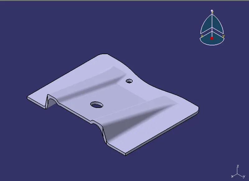
Tree Structure