Week 8 - Challenge 3 - Switch Bezel Design
DESIGN AND DRAFT ANALYSIS OF SWITCH BEZEL
OBJECTIVE
Create the Switch Bezel Plastic component through the given Class-A surface. To begin with, the tooling axis for the given Class-A Surface should be created meeting the requirements of the draft angle and at the end perform the Draft analysis on the model.
INTRODUCTION
The control panel bezel is the frame part of the window switch that holds its switch covers and buttons into place Moulding is the method used to manufacture the plastic terms of an automotive by most OEMs) hence by considering the manufacturing consideration the switch bezel is designed.
DESIGN CONSIDERATION
- Class-A surface should be aesthetically smooth and good
- Class-B surface should have all the supporting features like ribs
- Parting Line should coincide with the surface since flushing couldn't affect the aesthetic of Class-A
- The class-C surface should also pass the draft analysis
Procedure
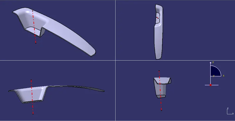
Step 1 Import class A surface.
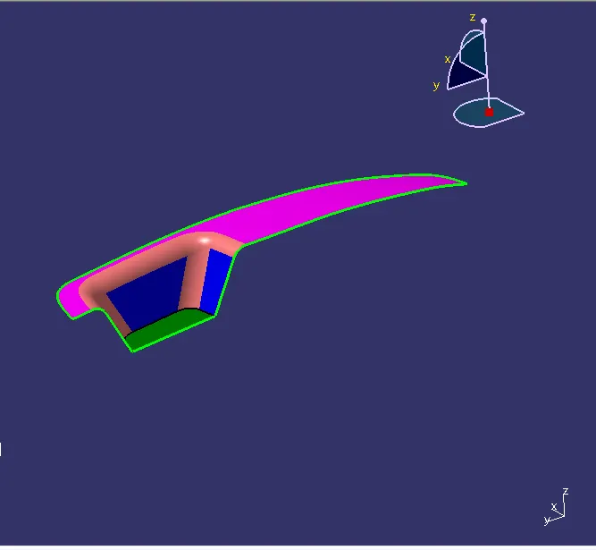
Step2 Creating a point ob base extract to put an axis system.
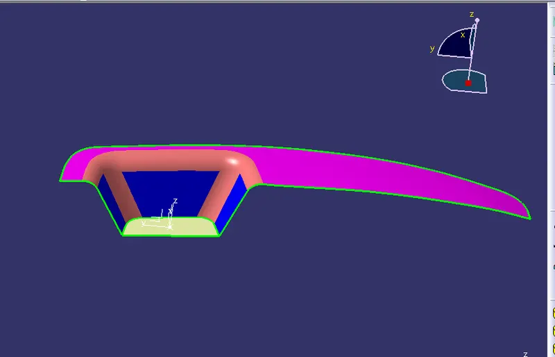
Step 2 Creating Tooling axis in first geometrical set by bisecting line command with reference to intersection sketch in YZ plane and ZX plane. The resulting axis is the tooling axis in the red dotted line.
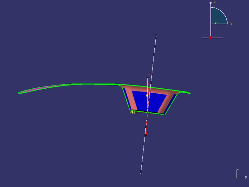
Publish Class A surface and tooling axis for ease of access.
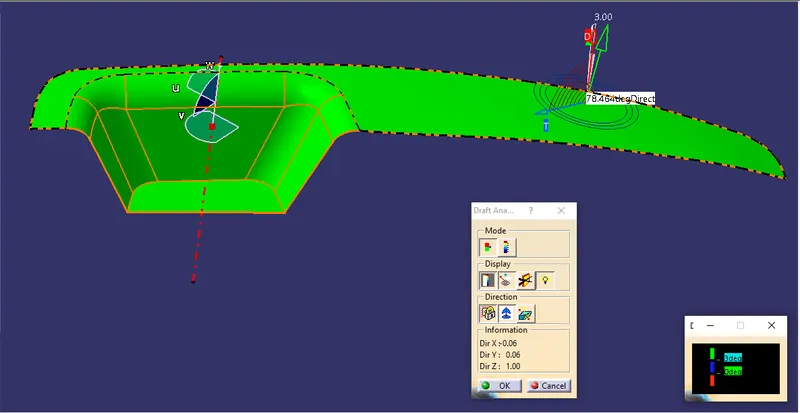
Perform Draft analysis on Class A
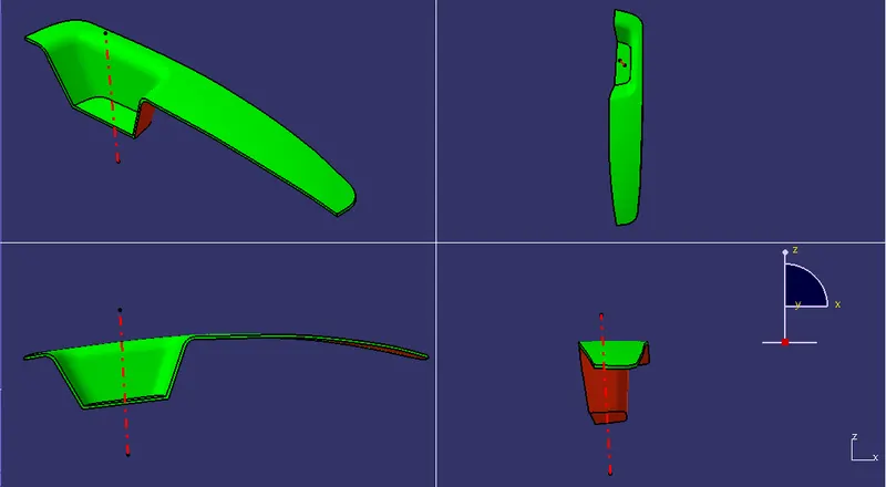
Switch to material mode and select draft analysis. Lock axis system with tooling axis in a such way that they are aligned together.
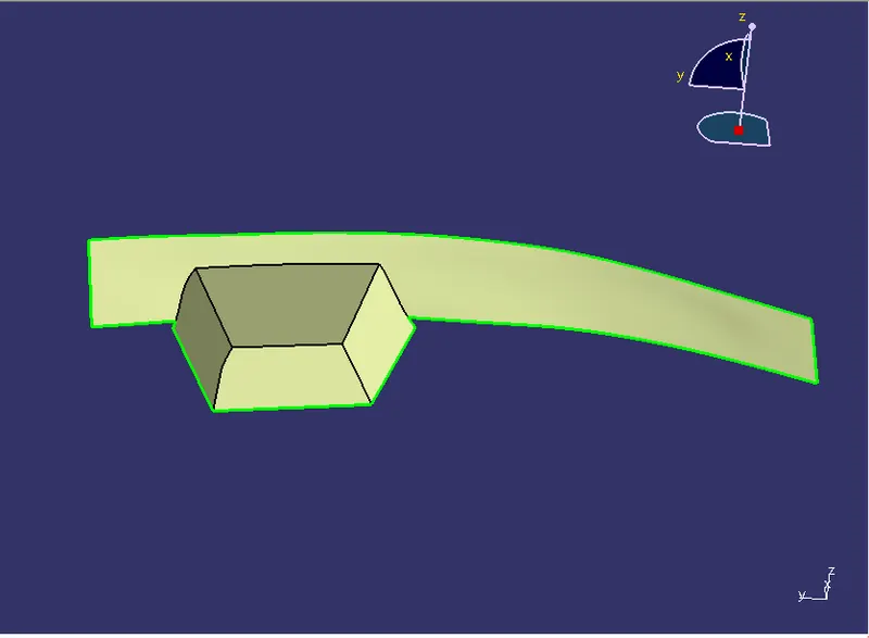
Creation of Class B surface.
Step 1 Divide class A surfaces into different sections.
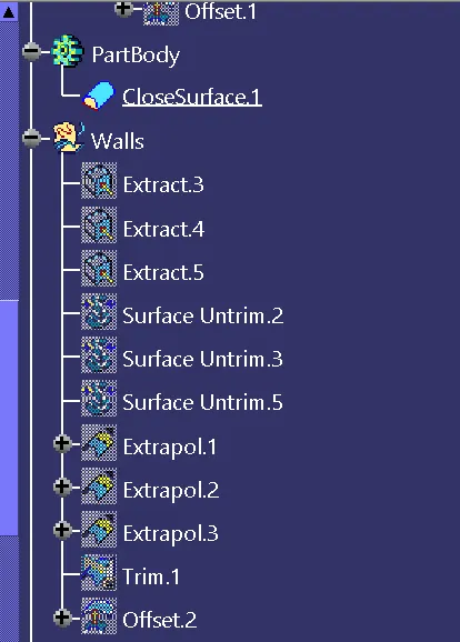
Step 2 Extract < Untrim < Extropolate each surface and trim together to get a class B surface.
Step 3 Offset the trim to 2.55 mm and carefully monitor the direction of the offset.
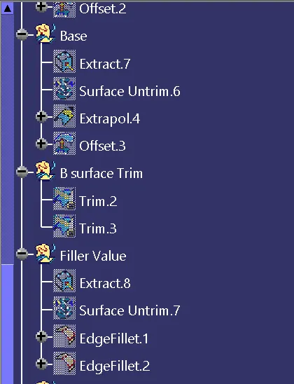
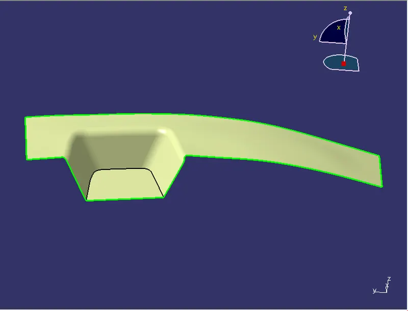
Perform surface trim operation to eliminate sharp edges.
Creation of class C surface
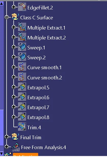
Step 1 Create the outer curve from the class A surface using multiple extract commands.
Step 2 Perform sweep command to extrude the curves along z-direction with tooling axis as the draft direction at an angle of 3 deg outward.
Step 3 Get rid of the uneven surface defects by performing curve smooth command and trimming them together to make it in a single trim.
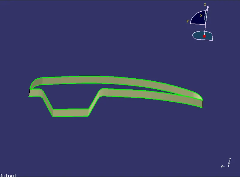
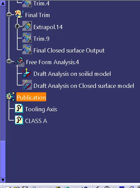
Final Closed Output
We will join Class A and Class C to remove boundaries and will trim them with class B to get the final closed output.
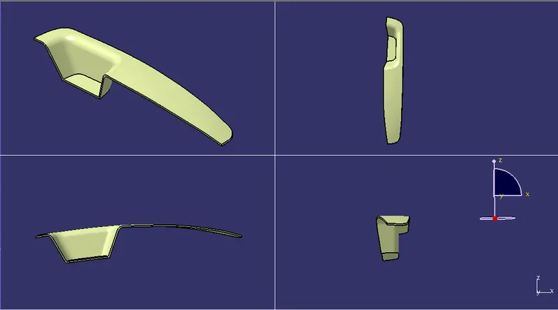
We will perform draft analysis on it by enabling material mode and locking axis system aligned with tooling axis.
Red color has draft less than 0 deg and green color more than 3deg.
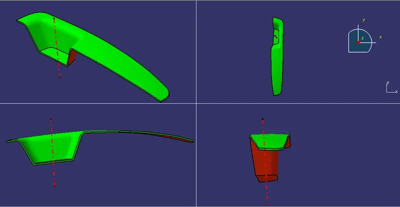
Create Solid model
Open part file .
Define work object in solid part body and choose closed surface option to form solid.
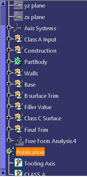
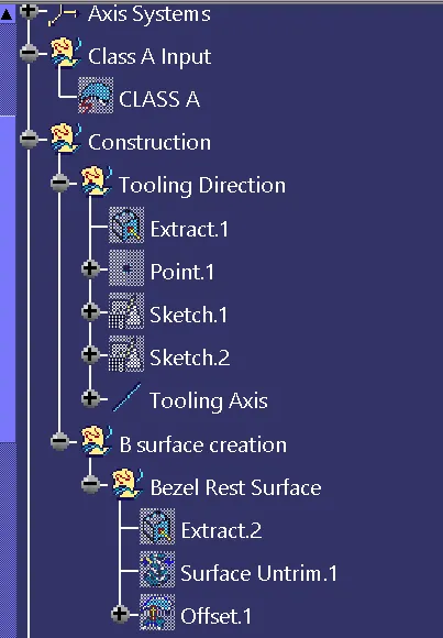
Tree Structure