Radar Mast & Final Assembly of Yacht
MODELING OF SUNSEEKER PREDATOR YACHT ON SOLIDWORKS
INTRODUCTION
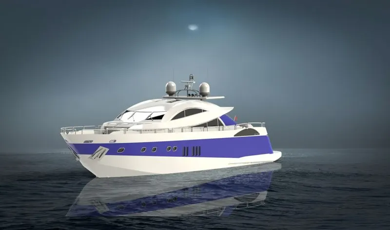
In this project, we are to learn the entire modeling of a Sunseeker Predator Yacht American chopper on solid works and solid works visualize.
A yacht is a sailor power vessel used for cruising or exploring via sea route. It usually comes in 33 ft. (10m) in length and has good aesthetics, amenities, and luxury. Medium size yachts are made from fiberglass while larger yachts are made of steel, aluminum, or composite fiber-reinforced plastic.
The different components of the yacht we deal with are:
- Propellor
- Radar
- Hull
- Garage and Garage Door
- Front seat
- Rear Seat
- Middle Seat
- Radar Mast
- Superstructure
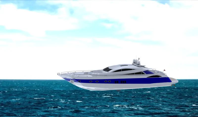
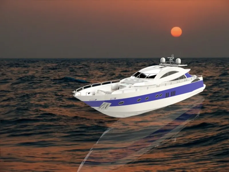
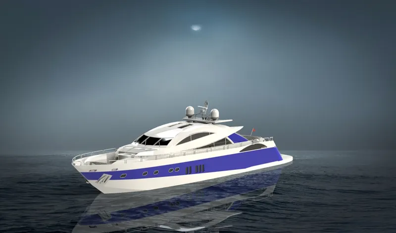
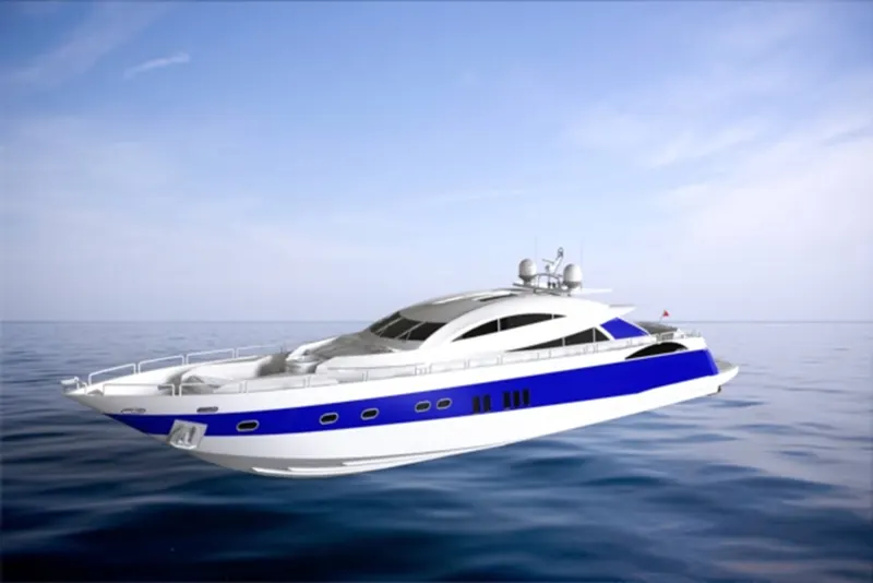
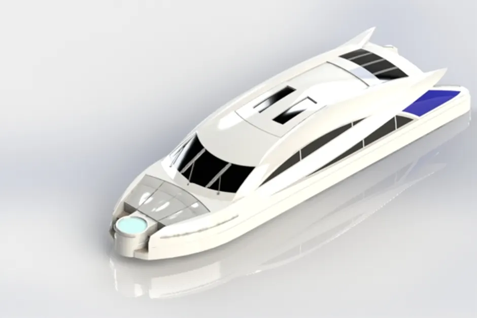
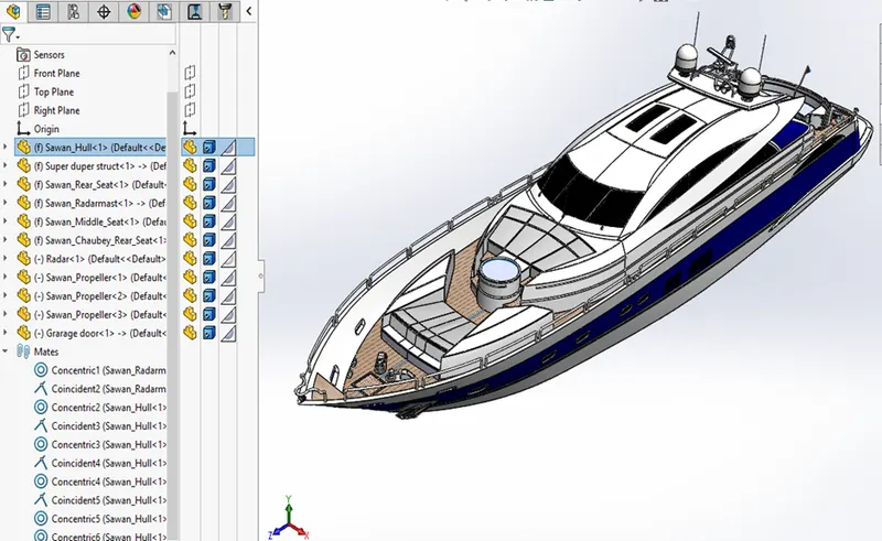
After designing the part components, we have worked upon the assembly and the photo rendering of the yacht which gives it a complete and realistic view.
DESIGN APPROACH
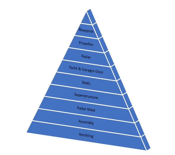
Starting with the Propellor and ending till the rendering section has been described step by step utilizing a flow chart.
Let’s discuss what are the features and properties used in the entire model to design different parts:
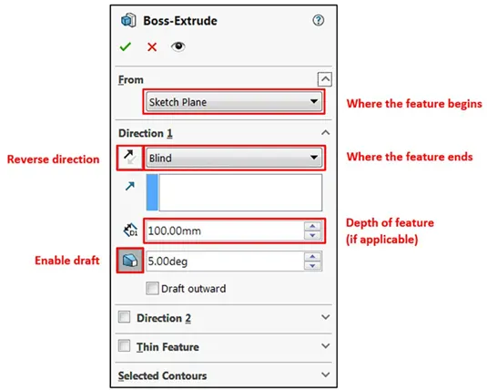
- Extrude Boss: The Extruded Boss is the most basic of all SOLIDWORKS features and extrudes a sketch along a straight-line path to add material. As a sketched feature, it requires a sketch before use. Once the sketch has been created, exit the sketch and select the Features tab of the Command Manager. Then, click the Extruded Boss/Base command. If a yellow dialog box appears in the Property Manager asking you to create a new sketch, don’t worry – simply click on the sketch in the graphics area to use it for the feature. The Property Manager for the Extruded Boss allows you to control starting location, extrude depth, and draft for the feature, among several other parameters:
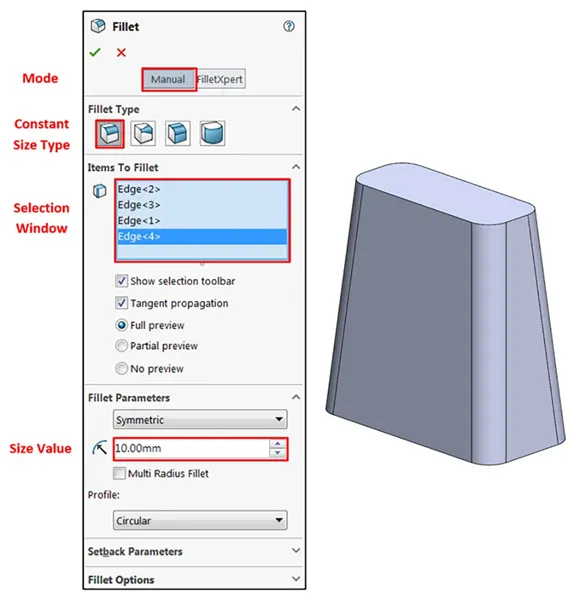
2. Fillet: Fillets are classified as applied features, and as such do not require a sketch to be used. Fillets serve to round off edges and/or corners by adding or removing material, depending on whether the edge is internal or external. It should be noted that fillets of different sizes must be created as separate features. Typically, it is best practice to create the largest fillets first and follow with smaller fillets.
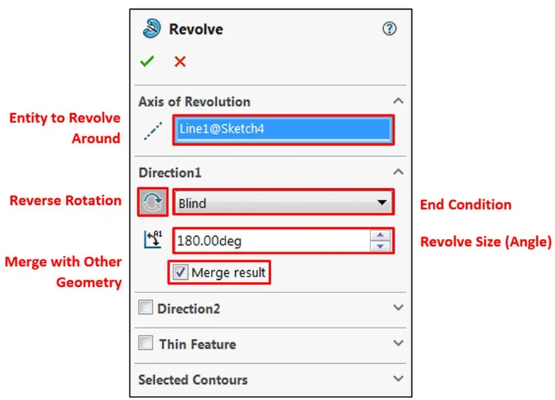
Revolved Boss Feature: Adds material by revolving a sketch around an axis. Remember, once geometry has been created in your model, any flat face can be used as a sketching surface. It is very important to draw an axis in the sketch which needs to be revolved.
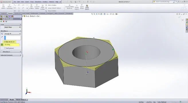
3. Extrude Cut: Similar to the extrude boss feature this feature needs a sketch on the solid body which needs to be cut and the desired shape is then cut off.
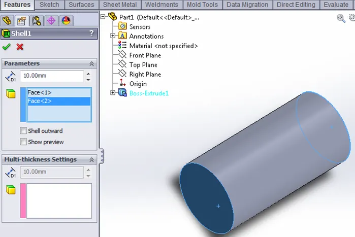
- Shell: SolidWorks shell tool is mainly used for the shelling process, in which the material is removed from the inner body of the model by keeping small thickness and results in a hollow model. Using this tool, you can make either a completely closed hollowed model or one face opened type.
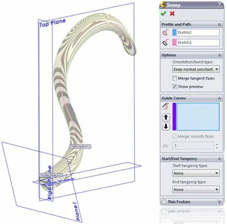
4. Sweep Boss / Sweep Cut: Sweep creates a base, boss, cut, or surface by moving a profile (section) along a path, according to these rules: The profile must be closed for a base or boss sweep feature; the profile may be open or closed for a surface sweep feature.
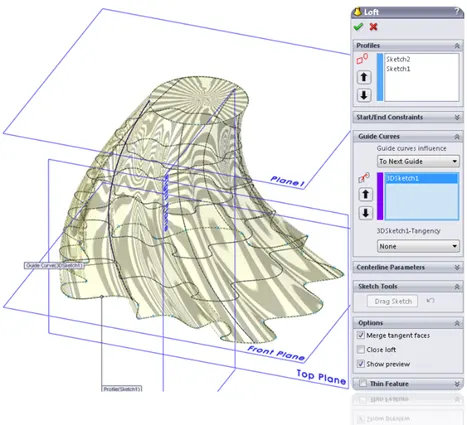
- Loft Boss/ Loft Cut: A loft feature is an important tool for (surface) modeling in SolidWorks. The loft feature creates a shape by making transitions between multiple profiles and guide curves. This tool is very valuable for modeling complex surfaces. You can do some cool stuff when you use this feature properly.
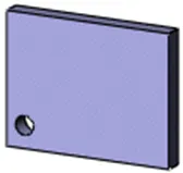
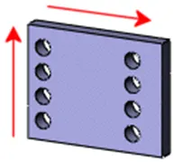
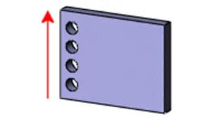
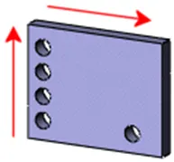
5. Linear Pattern: You can use linear patterns to create multiple instances of one or more features that you can space uniformly along one or two linear paths. Pattern instances inherit the visual properties of the original feature when you select Propagate Visual Properties in the Property Manager.
 |
 |
|
Seed feature |
Linear pattern - two directions |
 |
 |
|
Linear pattern - one direction |
Linear pattern - two directions Pattern seed feature only in Direction 2 |
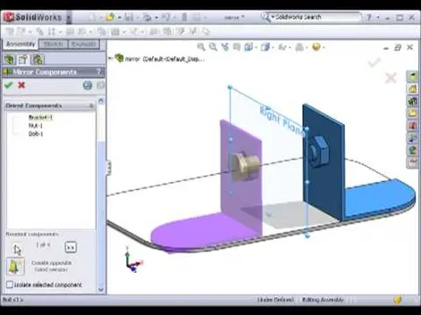
6. Mirror: Creates a copy of a feature, (or multiple features), mirrored about a face or a plane. You can select the feature, or you can select the faces that comprise the feature. Bodies to Mirror: Select a body in a single model or multi-body part to create a mirror entity. Multibody parts: Apply features to one or more multibody parts by selecting Geometry Pattern and using Feature Scope to choose which bodies should include the feature.
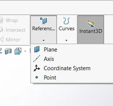
7. Reference Geometry: Reference geometry defines the shape or form of a surface or a solid. Reference geometry includes items such as planes, axes, coordinate systems, and points. You can use reference geometry in the creation of several kinds of features. For example, Planes are used in lofts and sweeps, An axis is used in a circular pattern.
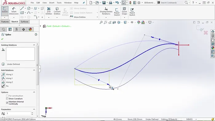
8. Projected Curve: You can project a sketched curve onto a model face to create a 3D curve. You can also create a 3D curve that represents the intersection of two extruded surfaces generated by creating sketches on two intersecting planes. You can create multiply closed or open-contour projected curves from a single sketch. You can also use 3D sketches as input for the Projected Curve tool. Note: the Projected Curve tool does not support projections of intersecting curves.
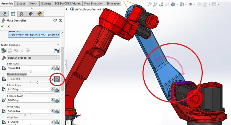
9. Mate: Mates create geometric relationships between assembly components. As you add mates, you define the allowable directions of linear or rotational motion of the components. You can move a component within its degrees of freedom, visualizing the assembly's behavior.
Some examples include:
- A coincident mate forces two planar faces to become coplanar. The faces can move along one another but cannot be pulled apart.
- A concentric mate forces two cylindrical faces to become concentric. The faces can move along the common axis but cannot be moved away from this axis.
Mates are solved together as a system. The order in which you add mates does not matter; all mates are solved at the same time. You can suppress mates just as you can suppress features.
Now as we have completed the discussion of how the features work under solid works let us see the application of the features in the Yacht that we have built. We are going to discuss part by part as shown in the flowchart.
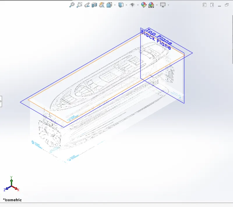
- Setting up Blueprints: Blueprints were imported into Solidworks part by the following path. Tools – Sketch Tools – Sketch Picture. Then dimension was given to position the blueprints according to the planes. This setup was used to create all the components of the yacht.
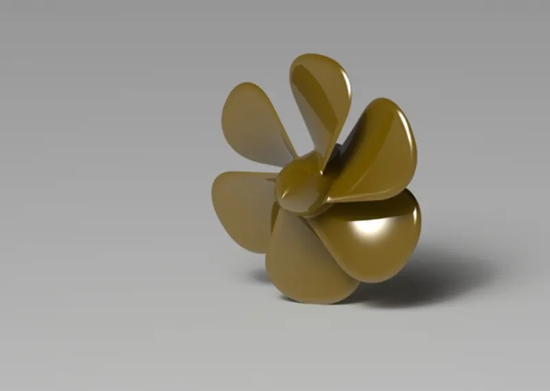
2. Propellor: The solid component, consisting of a hollow cylinder of a certain thickness, has fan blades mounted over the outer surface of the cylinder is called a propellor. The main function of the propellor is to exert thrust by rotating of fan blade under the water so that the yacht can move forward.
- It was modeled by using solid features such as Revolve Boss/Base, Extrude cut, etc.
- First, a blade is modeled using the Lofted Boss/Base feature. Then, the blade is mirrored using the circular pattern feature.
- Further, the fillet feature is used to remove all sharp edges.
- Finally, appearance is given to the propellor and the file is saved.
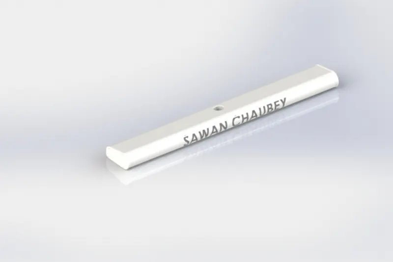
3. Radar: It is a navigation tool used in yachts. Radio detection and ranging (RADAR) helps ships to detect objects far away by using radio waves. It is very useful in bad weather for navigation. It sends radio waves in all directions and when the signal hits an object then its info is displayed on the screen. Hence the pilot can steer away to avoid any collision or accident.
- It was modeled by using solid features such as Revolve Boss/Base, Extrude cut, etc.
- The fillet feature is used to remove all sharp edges.
- As the Radar is symmetric in shape. Therefore, half part was modeled and the other half was mirrored using the Mirror feature and both solids were merged in the operation.
- Also, the text is added to the Radar to give it a realistic look. The text was projected on the surface of the radar using the Split Line feature.
4. Hull: Hull is a bottom floating body of a yacht that meets the water line below and is open above. Surface modeling was used to model Hull. I used project curves, surface extrudes, trim surface, lofted surface, knit surface, and other surface and solid features to design a yacht from a 2-D to 3-D model. First, we created Blueprints from different planes then we created 2-D sketches and converted 2-D to 3-D by using surface features. Then we created a solid body from the surface body and knitted together the different components of the hull. Only half portion of the hull was modeled and the other half was mirrored using the mirror feature as it is symmetric. Fillets were used to eliminate sharp edges and give them an aesthetic appeal. The appearance was given for a realistic look.
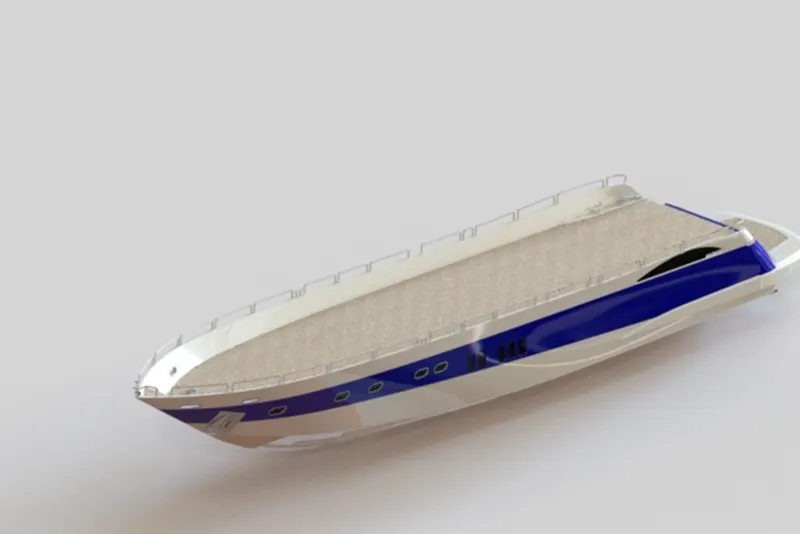
5. Front Seat: I have designed the front seat by using features likes Boss extrude, surface extrude, surface cut, trim surface, project curve, and other commands in Solidworks. First, I created a 2-D sketch by referring to the blueprints. Then I converted it into a Solid model by using a knit surface and forming a solid feature.
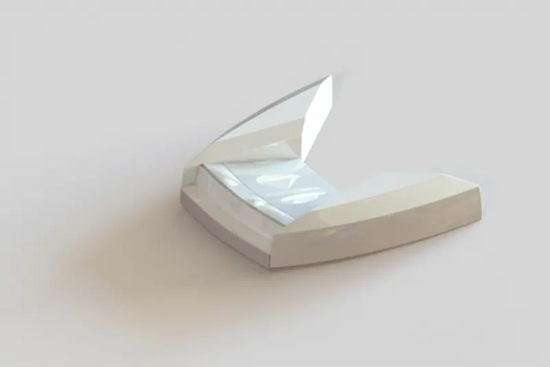
6. Rear Seat: I have designed the front seat by using features likes Boss extrude, surface extrude, surface cut, trim surface, project curve, and other commands in Solidworks. First, I created a 2-D sketch by referring to the blueprints. Then I converted it into a Solid model by using a knit surface and forming a solid feature.
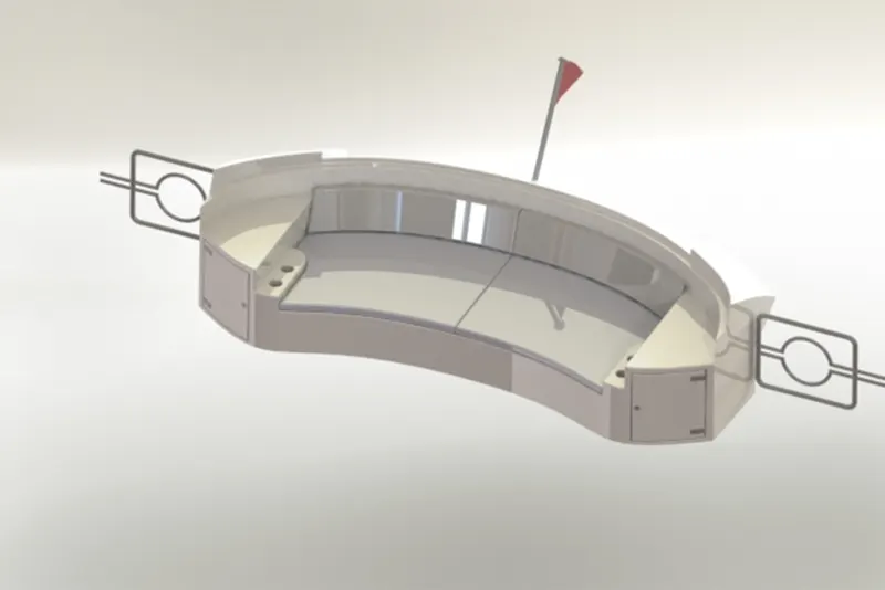
7. Middle Seat - I have designed the front seat by using features likes Boss extrude, surface extrude, surface cut, trim surface, project curve, and other commands in Solidworks. First, I created a 2-D sketch by referring to the blueprints. Then I converted it into a Solid model by using a knit surface and forming a solid feature. Fillets were used to eliminate sharp edges and give them an aesthetic appeal. The appearance was given for a realistic look.
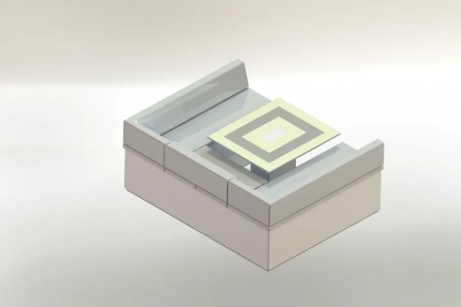
8. Superstructure: Superstructure is the upper part of the yacht, which is attached to the hull and gives a complete look to the yacht. I have designed the superstructure by using the project curve from referring to the blueprints. Project curve helps to create a curve in 3-D from a 2-D sketch. By using surface features, I created a closed hollow superstructure body. Then merged all the surfaces, knitted them, and formed a solid superstructure. Afterward, I had given appearances to different parts of the superstructure. Only half portion of the superstructure was modeled and the other half was mirrored using the mirror feature as it is symmetric. Fillets and Chamfers were used to eliminate sharp edges and give them an aesthetic appeal. The appearance was given for a realistic look.
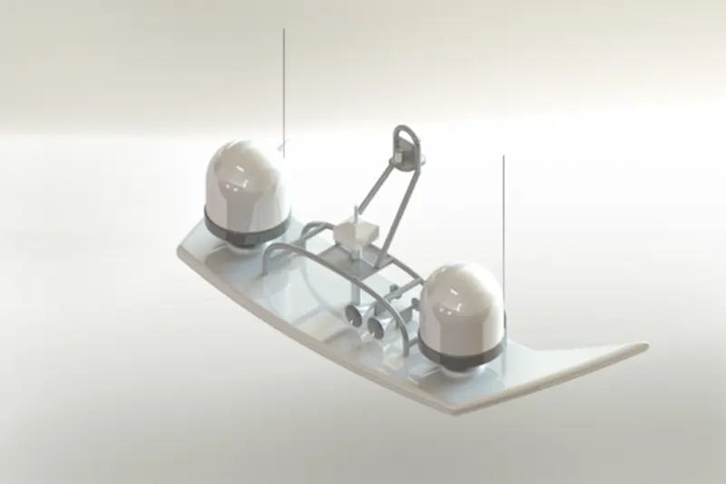
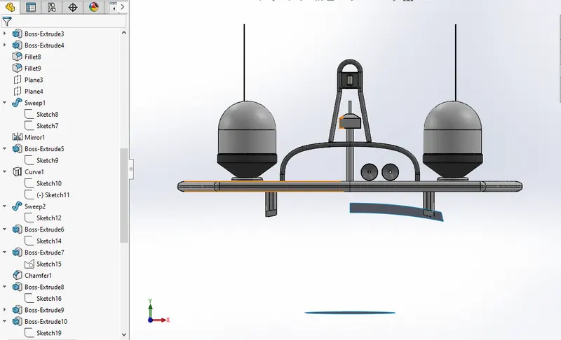
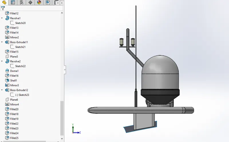
9. Radar Mast: The design starts with outlaying the sketch of the base of the pedal on the front plane and an extruded boss is created with dimensioned circular holes for the footrest and the pins which are extruded the second time, now a sketch is created on the top plane for the footrest which is then revolved to make a 3d image the top of the rest is applied with a dome and the edges and joints are filleted to avoid sharp cuts, the front and the rear extruded cylindrical parts are then chamfered to attain a proper finish and a circular pattern is extruded on each of the front-facing extrudes which are then arranged using linear pattern and fillet is applied to all the edges and the joints of the last pattern.
Assembly of Yacht
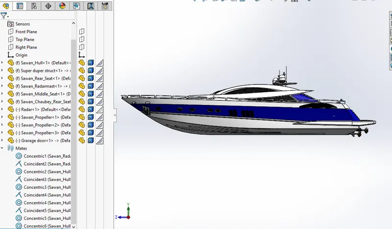
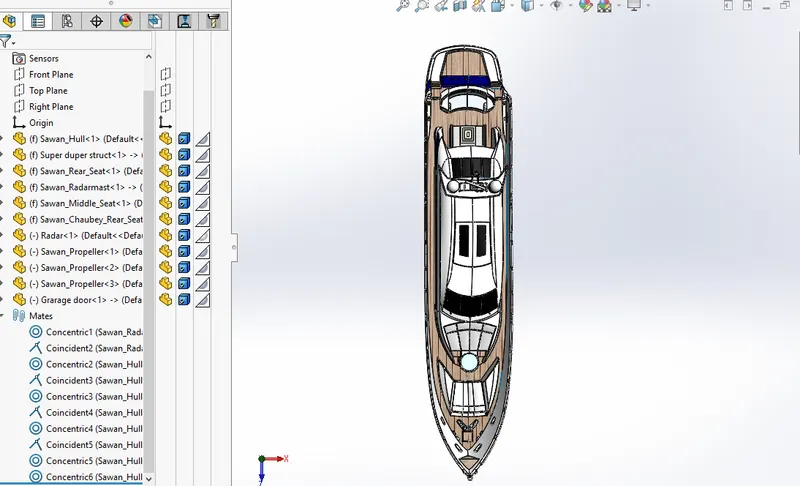
First, we opened an assembly file in Solidworks and imported the hull then all other parts were fixed to the hull. We used mates like incident, concentric and parallel to assemble the yacht. After assembly, we Rendered the Yacht in photoview360.
Rendering
Rendering was done on photoview360 and lighting was set according to the environment. Photoview360 is an additional rendering tool of Solidworks.