Week 8 - Challenge 1 - Draft Analysis on a Fan Cover
Draft Analysis on a fan cover
To create the tooling axis for the given Fan Cover model meeting requirements of the draft angle and performing the draft analysis on the model meetings the requirements of the draft angle and performing the draft analysis on the model.
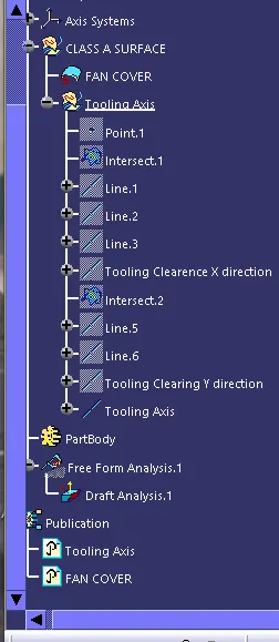
Objective: Ensure Proper Tree Structure
- Geometrical sets should have a proper name based on the sketches present inside of it
- All the sketches should be created under the Geometrical set
- Publications: Use the publication option and publish the below
- Tooling Axis
- Class A surface
Procedure:
Step1. Import the class A surface model.
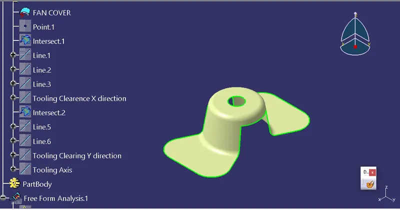
Step 2: Check for boundaries
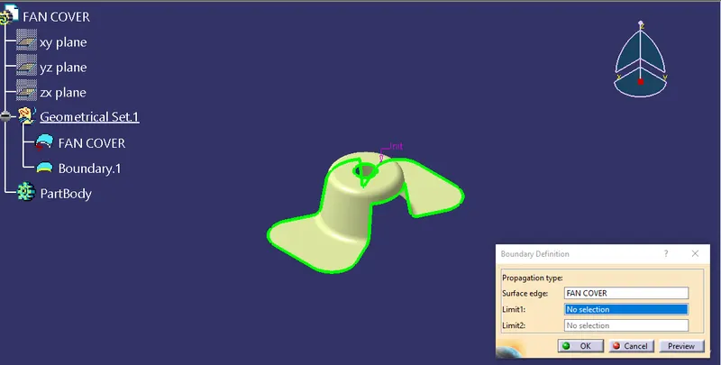
Step 3: Create a point on upper center hole and create a axis system on that point.
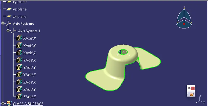
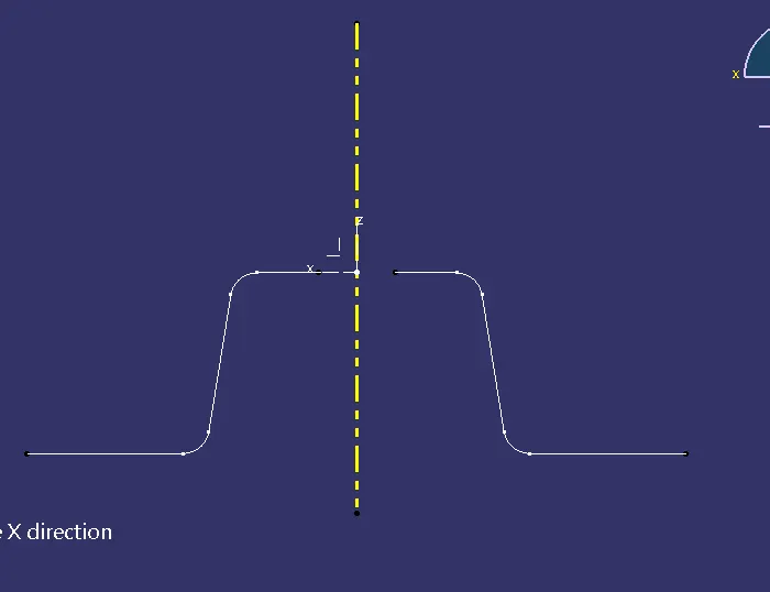
Step 4: Create 2d sketch of FC viewing from X direction by selecting intersection command with reference of zx plane and FC.
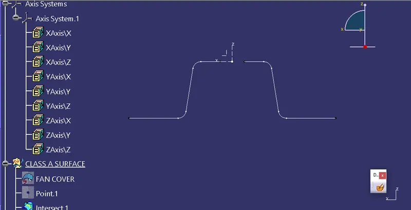
STEP 5: Create lines tangent with both horizontal walls using line command, point to point as reference.
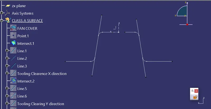
Steps 6: Similarly using intersect option, select the yz plane of the axis system to form tooling axis clearing y-direction.
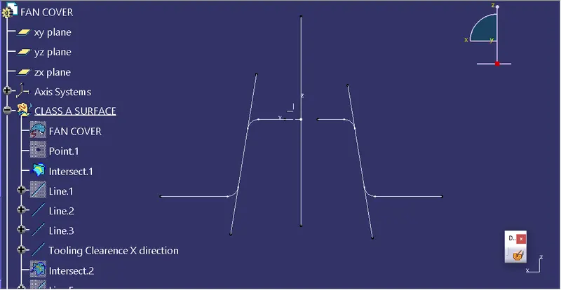
Step 07: After the two axes are formed. Create the final tooling axis in the z-direction.
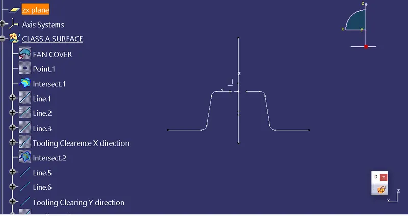
We got the final tooling axis in z-direction represented with the yellow dotted axis.
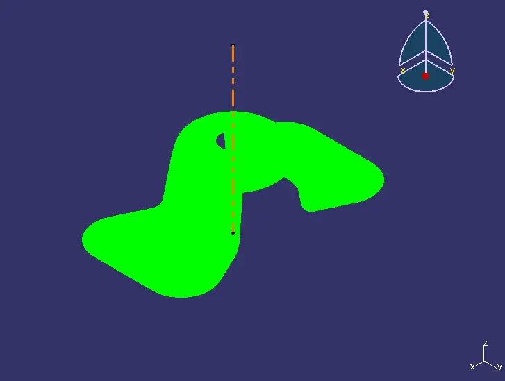
Now, We will perform a draft analysis. Menu > Insert > Analysis > Feature Draft Analysis. Align compass with the tooling z-axis. Select a green color from the draft box and give a 3-degree value of draft and click enter. Publish the fan cover and tooling axis by selecting tools publication.
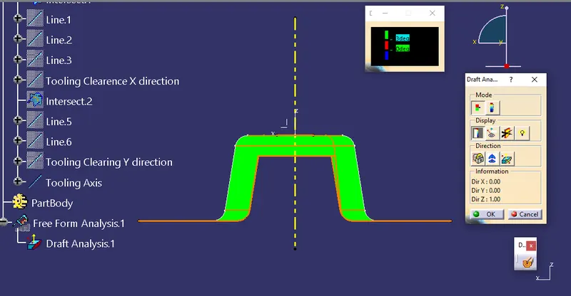
Front view
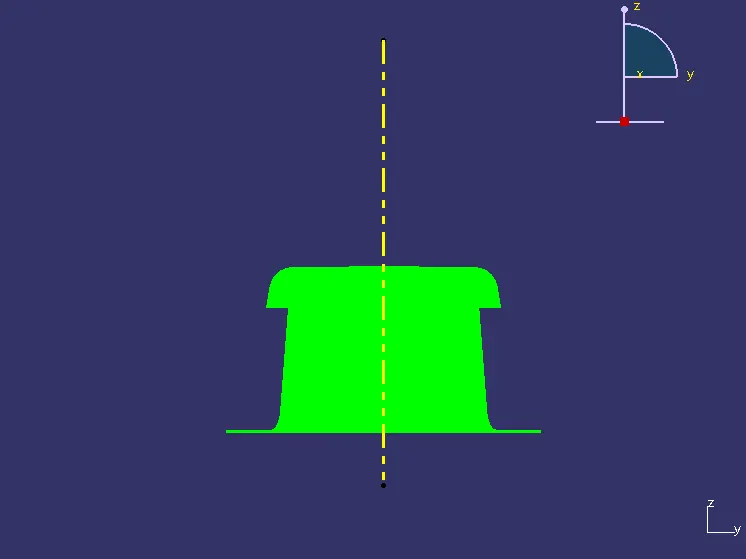
Top View

Isometric View
Tree Structure