Week 9 - Attachment Feature Creation - Challenge 1
RIB DESIGN IN COIN HOLDER
1. Tree Structure and The Geometrical Sets
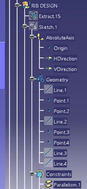
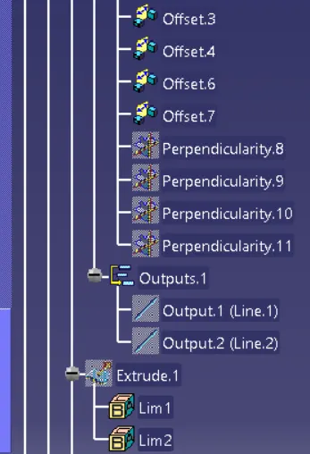
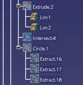
2. The Various Oreintation View of Ribs
- Front View
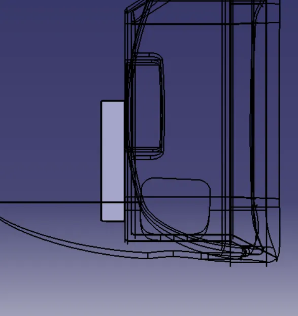
- Side View
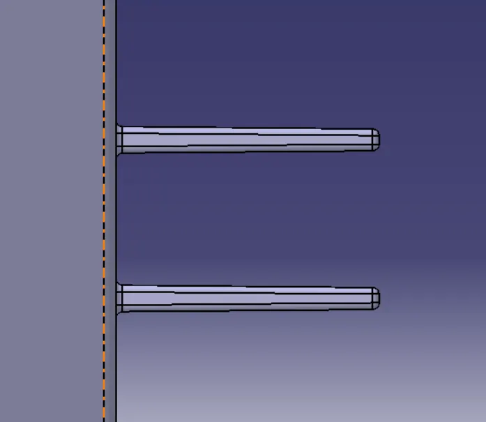
- Top View
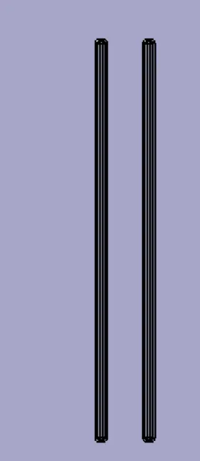
- Isometric View
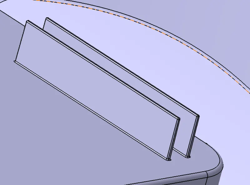
3.Tooling Axis
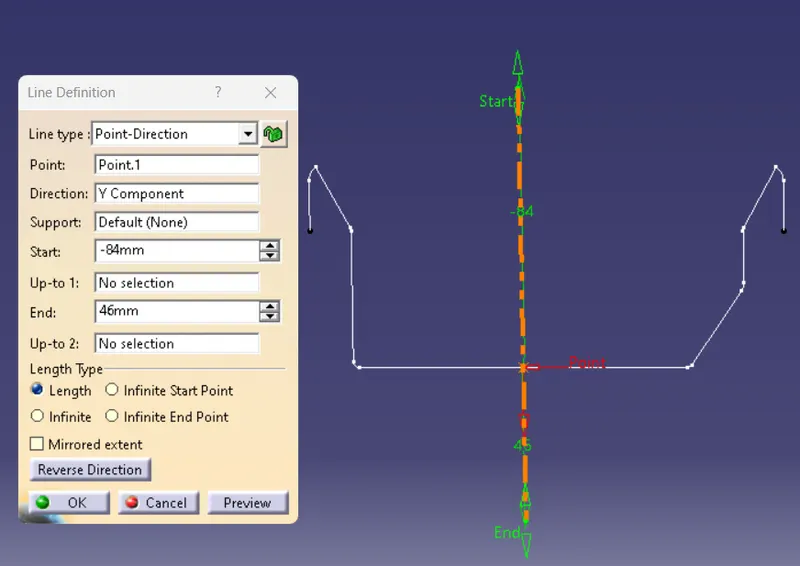
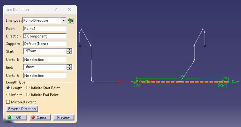
4. Rib Design in Coin Holder
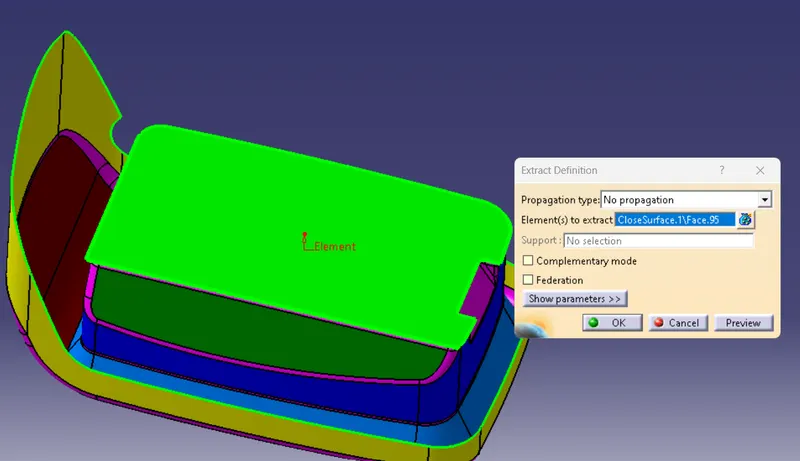
Extract the Bottom Surface From the Class A to Create a Rib on it.
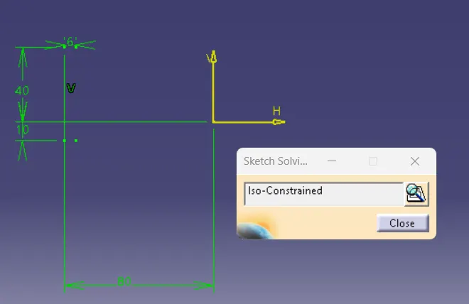
Create a sketch for th rib where it as been go to place.
The Height of the rib is 5 times from the Wall thickness.
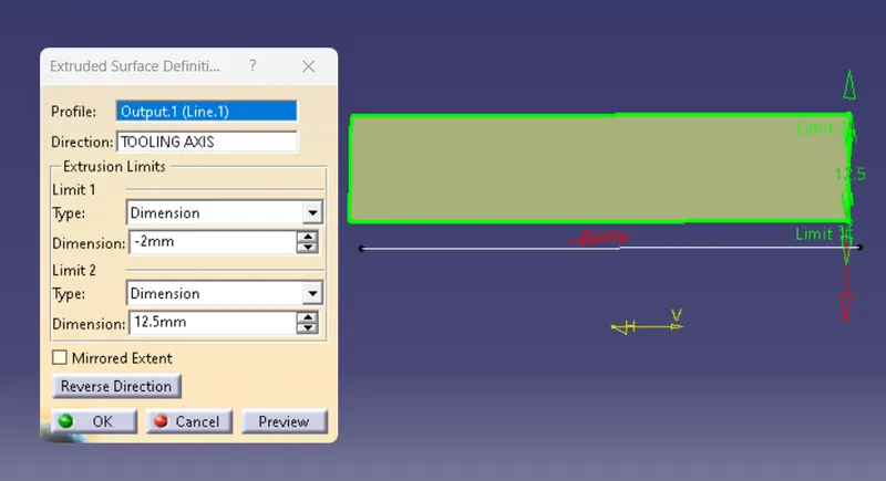
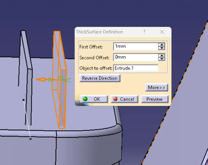
The Thickness of the rib is 1mm
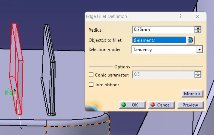
The Fillet should given is 0.25mm from rib creation standard.
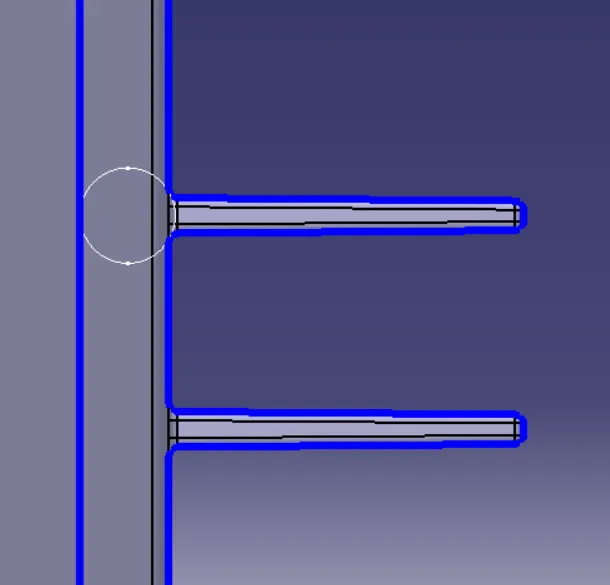
Avoid the sink mark
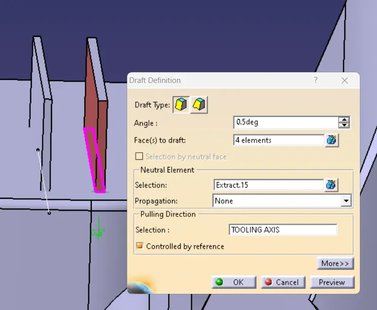
The Minimun Draft of the Rib is 0.5 degree
5. Detailed Report for the Rib Creation
Rib Basic Industrial Required
- Normal wall thickness of a Plastic Component is 3mm
- A deviation of +30% from the wall thickness is accepted
Example for 3mm thickness
2.1mm is Minimum
3.9mm is Maximum
- Ideal Draft for a Component is 3 Degree
- Minimum 0.5 degree accepted in Ribs
Ribs Provide a Means to Economical Stiffness in Molded part without increasing overall wall Thickness.
They also facilitate :
- Locating and Arresting Component of an Assembly
- Providing aligment in mating part
- Acting as stop or Guide for machine.
The Section deal with general guiding for the rib and part design
Proper Rib Design involve five main issues:
- Thickness
- Height
- Location
- Quantity
- Manufacturability
Consider there issue carefully when the Rib Design.
Rib Thickness
In our model the thickness 0.25mm
Height of the Rib 5 times from wall thickness. the thickness 0.4*t
To Avoid the sink mark the rib thickess should in the proper Guideline.
The Minimun Draft of the Rib is 0.5 degree.