Radar Mast & Final Assembly of Yacht
RADAR MASTER
Max Expected Number of required hour to desgin - 1.5hrs
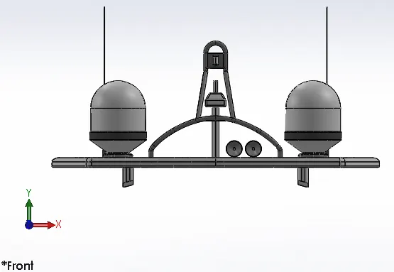
1. Radar Mast Front View
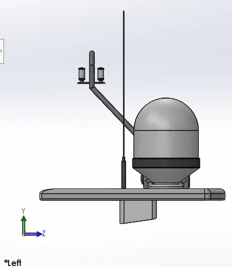
2. Radar Mast Side View
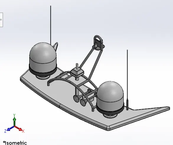
3. Radar Mast Isometric View
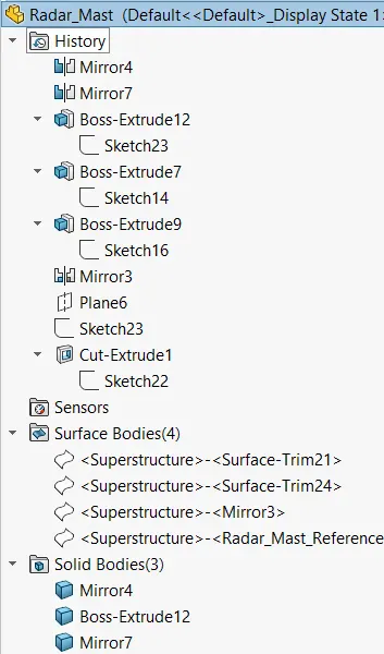
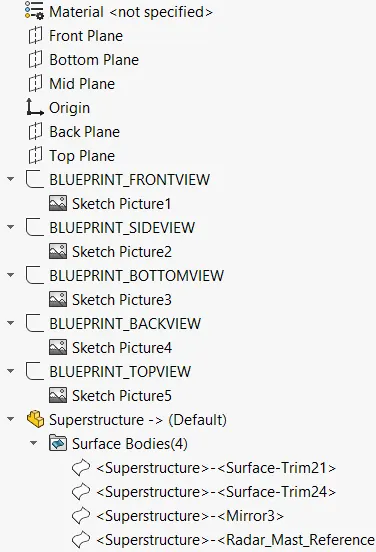
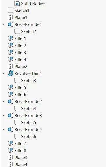
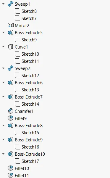
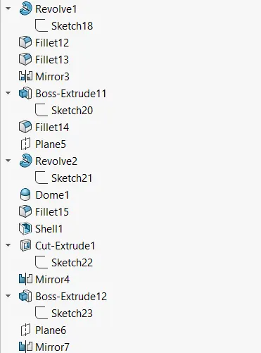
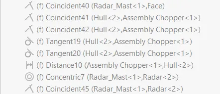
4. Radar Mast Feature Tree
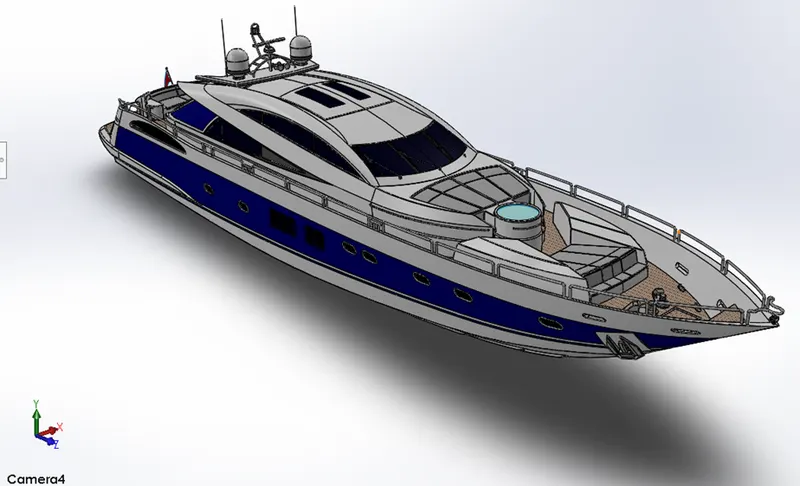
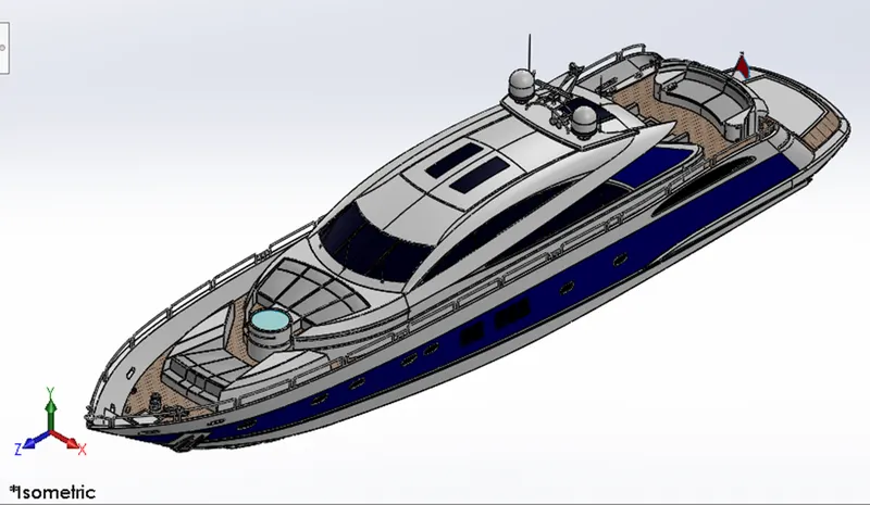
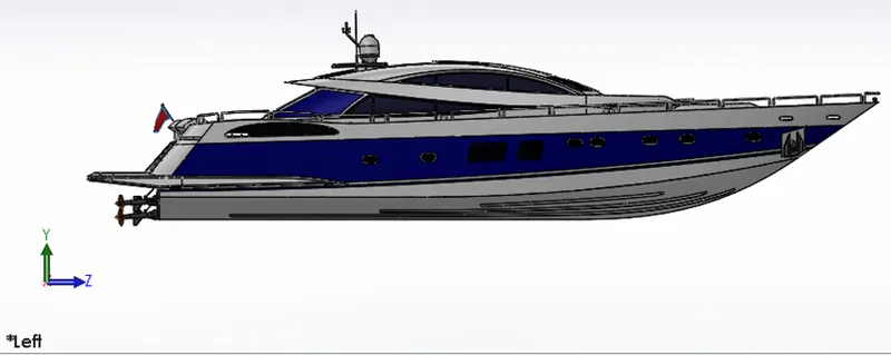
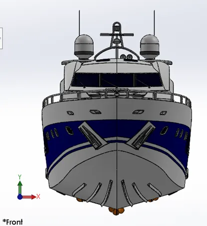
YATCH ASSEMBLY
Max Expected Number of required hour to design - 8hrs
Surface Modelling, Assembly and Photo Realistic Rendering of Yacht
Objective:
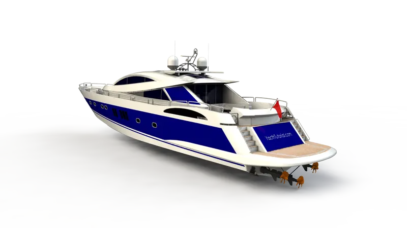
To model parts of yacht and assemble them in SolidWorks. After the assembly, the yacht is then rendered for photo realistic view using SolidWorks Visualize.
Introduction
SolidWorks is a 3D modelling software developed by Dassault systems. It enables the user to create/model parts, assemble them and sheet metal design etc., The designing of model is achieved by using various feature in the software and used feature have been listed below:
Commonly used feature in Part design:
- Part design has two types of features i.e., sketch tools and 3D feature.
- Sketch tools consists of 2D elements like line, Polygons (different types of rectangles), Circle, Arcs, Spline (a 2D line which can be control points), etc.,
- A 3D feature converts the sketch or 2D element into a 3-dimensional object by using feature like Extrude, Extrude Cut, Revolve Bass, Revolve Cut, Sweep, Lofted Base etc.,
- Surface is a two-dimensional object with zero thickness.
- Most of the parts are designed using surface and then the surface are converted into solid by adding thickness.
The design approach starts with a sketch of desired which is Yacht in this case. The sketch will act as reference or blueprint for the 3D modelling of complex parts which cases the job of Modelling.
The components of Yacht in this design are:
- Propeller
- Radar
- Hull
- Rear Seat
- Front Seat
- Middle Seat
- Radar Mast
- Superstructure
- Garage Door
The most commonly used feature while designing/modelling these parts are discussed below:
Extrude Surface: Create a surface of a one-dimensional objects like line, curve, spline, etc.,
Revolved Surface: Creates Surface around an axis/defined line.
Swept Surface: Creates surface of a profile along a path.
Loft Surface: Creates surface of two profiles. The shape of surface can be altered by using guide curves.
Boundary Surface: Creates boundary surface of open edges.
Filled Surface: Creates a surface of closed boundary.
Offset Surface: Create a surface parallel to an existed surface at a defined distance.
Ruled Surface: Create a Surface on an edge. It can be tapered/normal/tangential with respect to the defined edge/surface
Delete Face: Deletes the selected surface. It can also be used to fill/patch the delete surface.
Extended Surface: Extends the surface upto a defined or specified vertex/ surface
Trim Surface: Deletes the unwanted surface with reference to a specified surface or sketch.
The selected surface either be deleted or kept according to the design
Knit Surface: Combine different surfaces into a single surface body.
Fillet: Replaces the sharp corners with a circular surface.
Thickness: Adds thickness to the surface.
Extrude: It is a 3D feature which will be used in small most every part design. It adds thickness to a given sketch or 2D drawing. Depending upon the requirement of design, different types of extrudes are available.
Extrude Cut: It is similar to the extrude except it removes the material from the object. It also has different types depending upon the types of removal.
Revolve: This feature is used to generate circular bodies around an axis. When a cross is revolved around an axis by adding material, then 3D object is produced.
Revolve Cut: It removes the material from an object in a revolved manner about an axis. The required cut of the material by revolving a cross-section around desired axis.
Sweep: Its is produces 3D objects of uniform cross-section from two sketches of which one acts as across section, and another sketch acts a guide curve or center line which guide the given cross-section throughout the span. The cross-section can be rectangle, circle, square, or any closed path while the guide curve may be straight line, spline, or arc, etc.,
Lofted Base: It produces 3D objects from the sketch which are on different planes. Objects with Variable cross-section are produced using this feature. The path of cross-section of the object can be monitored by guide curves.
Combine: By using this feature, Solid of different shapes or cross-section can be combine to generate a new complex design.
Split: When two bodies are merged into an another, by using split feature they can be separated or to avoid the surface of an object, split can be used to avoid the merging.
Plane: This feature is used to generate new planes as it is not possible to create body on the given planes.
Mirror Entities: This feature is used to mirror the bodies or feature with refence to an axis or the plane.
Patterns: This feature is used to copy an object for multiple times in a single operation. There are different types of Patterns like Linear pattern, Circular pattern and Spline or curve driven pattern.
Fillet: This feature eliminates the sharp edges by adding a rounded edge. It can be either constant radius fillet or variable radius fillet.
Chamfer: This feature also eliminates the sharp edges but by adding a sloped edge. It can be added by giving the distance from edge onto two face or depth of chamfer with an angle.
Dome: This feature provides concave surface on flat surfaces.
Shell: This feature produces the hollow parts for solid bodies with defined thickness.
Design Approach:
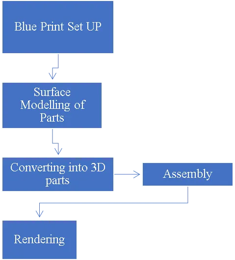
- Assembly:
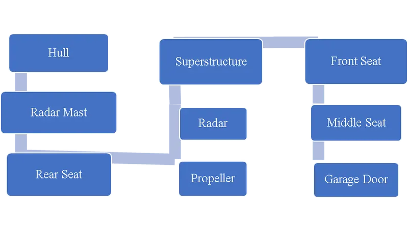
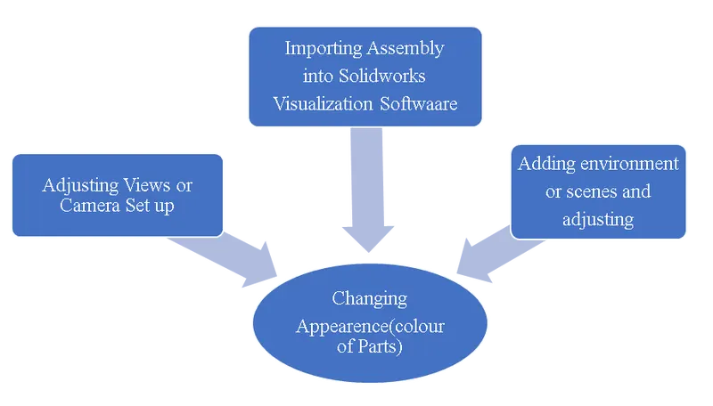
- Rendering:
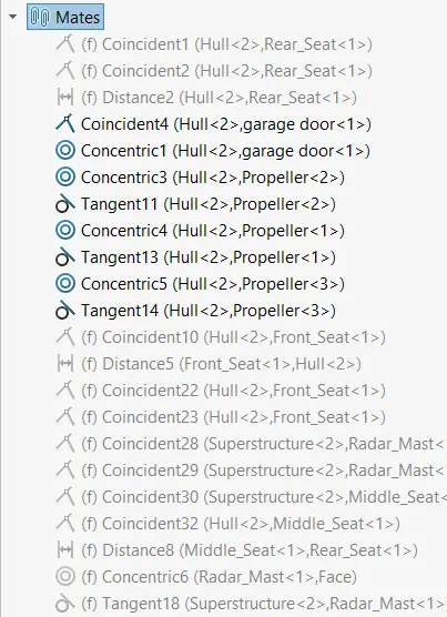
- Feature Tree :
PART DESIGNING:
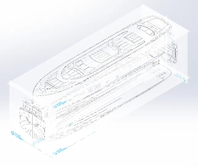
1.Blueprint Setup: It acts as reference for the part designing. The sketch picture is imported and adjusted to match with the dimension of part to be designed. It is made transparent to be able to view the objects behind it.
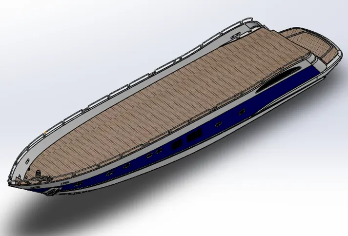
- Hull: It is the main part of the yacht. It provides accommodation for other parts like Seats, Superstructure, Garage Door, etc., The body of hull is modelled using surfaces and then it is converted into solid.
- Surface Operations
- Sweep Surface
- Loft Surface
- Boundary Surface
- Knit Surface
- Trim Surface
- Delete Surface
- Projection Curve
- Reference Planes
- Solid Operations
- Extrude
- Extrude Cut
- Split
- Dome
- Fillet
- Chamfer
- Mirror
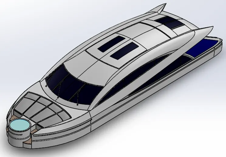
- Super Structure: It is the extended part of hull and facilities the accommodation of driver cabin. It is also modelled using surface and then converted into solid.
- Surface Operations
- Extrude Surface
- Sweep Surface
- Extended Surface
- Loft Surface
- Boundary Surface
- Fill Surface
- Knit Surface
- Trim Surface
- Delete Surface
- Projection Curve
- Reference Planes
- Solid Operations
- Extrude
- Extrude Cut
- Dome
- Fillet
- Chamfer
- Mirror
- Radar Mast: It placed on the superstructure to detect objects in the path of yacht so thereby avoiding collisions. It is designed in solid modelling
- Extrude
- Extrude Cut
- Revolve
- Sweep
- Shell
- Reference Planes
- Projection Curves
- Dome
- Mirror
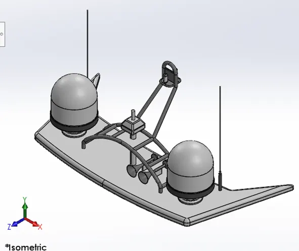
- Radar: It is a part of Radar mast and used to detect objects
- Extrude
- Extrude Cut
- Mirror
- Fillet
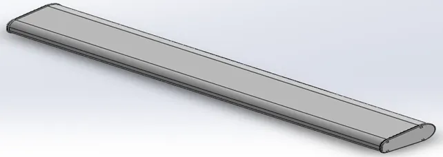
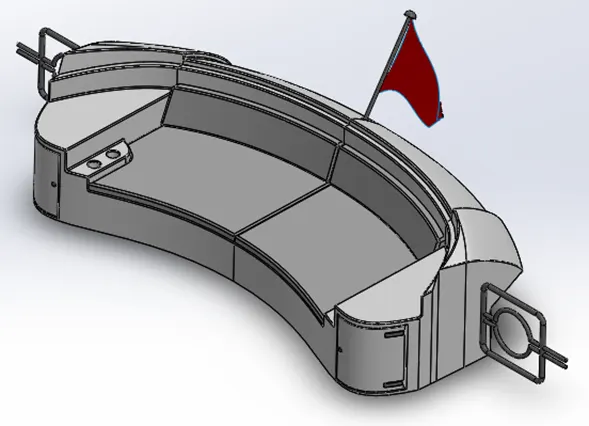
- Seats: These facilities the seating of passenger during the journey. These are named after their position in the yacht, i.e., Front, Middle and Rear Seat.
- Surface Operations
- Extrude Surface
- Sweep Surface
- Extend Surface
- Loft Surface
- Boundary Surface
- Fill Surface
- Knit Surface
- Trim Surface
- Delete Face
- Projection Curve
- Reference Planes
- Solid Operations
- Extrude
- Extrude Cut
- Dome
- Fillet
- Chamfer
- Mirror
Front Seat
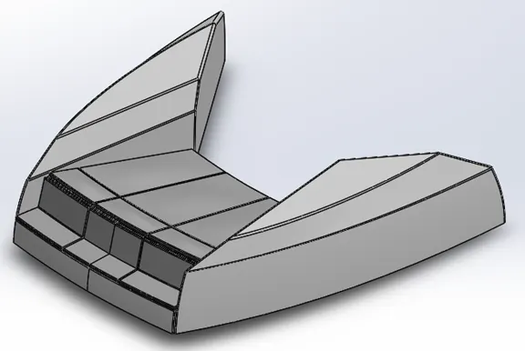
Middle Seat
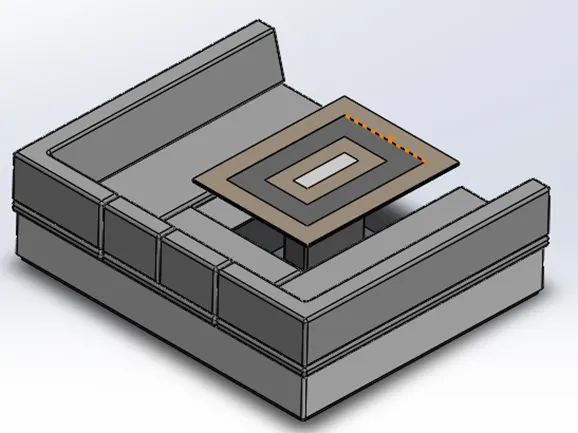
Rear Seat
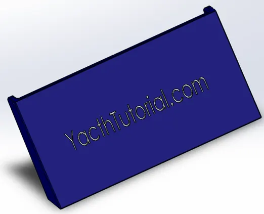
- Garage Door: It is used as closure for garage or storage room.
- Extrude
- Extrude Cut
- Mirror
- Chamfer
- Fillet
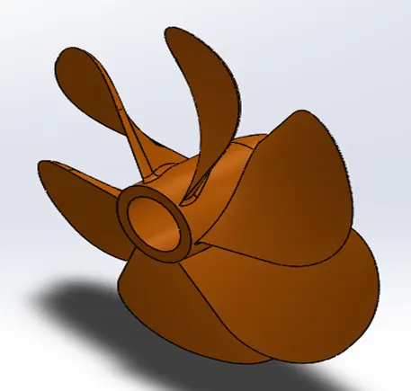
- Propeller: It used to create thrust to propel the yacht. The thrust is created by the rotating blades
- Revolve
- Loft
- Circular Pattern
- Fillet
ASSEMBLY:
After the completion of part modelling, the next step is assembly of those into a yacht.
The relation between the parts is defined by mates. These are different types of mates in the assembly;
- Concentric Mate
- Coincident Mate
- Parallel Mate
Parts like super structure and seats are designed using a surface from hull. When these parts are imported into assembly workbench, they are fixed automatically at their positions without any mates. Or they can be fixed by using mates.
Radar Mast is designed using a reference surface of Super Structure, so it is automatically fixed on the superstructure.
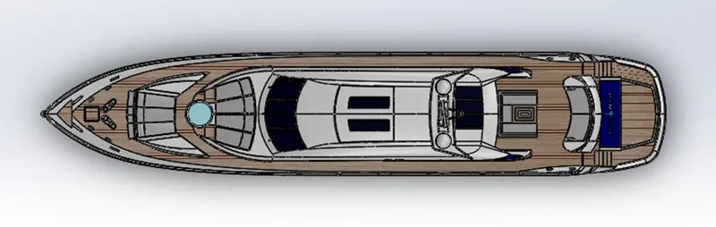
* Top
*BACK
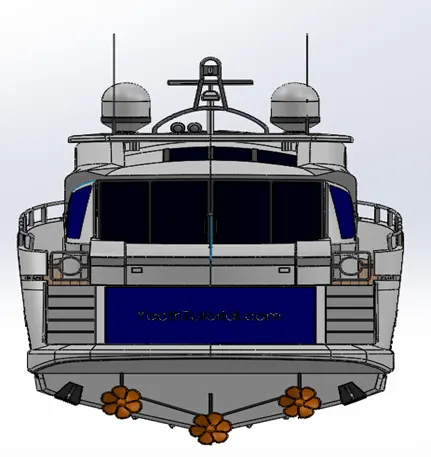
Appearance of parts is done in assembly to have an idea about design or materials of the parts. Different appearance is assigned to the parts according to their nature.
Decals are imposed on the surfaces of the parts to give it an aesthetic look. These can be images or pattern or any kind of design according to the choice of designer/owner.
Note:
- The sketch should be fully defined i.e., the position of entities must be defined fully with respect to origin or any other reference like construction lines.
- Avoid the mates between planes of parts and assembly planes. Instead create mates with respected to main component (for example: chassis).
RENDERING:
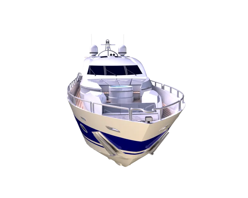
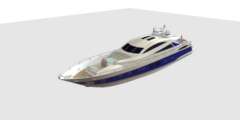
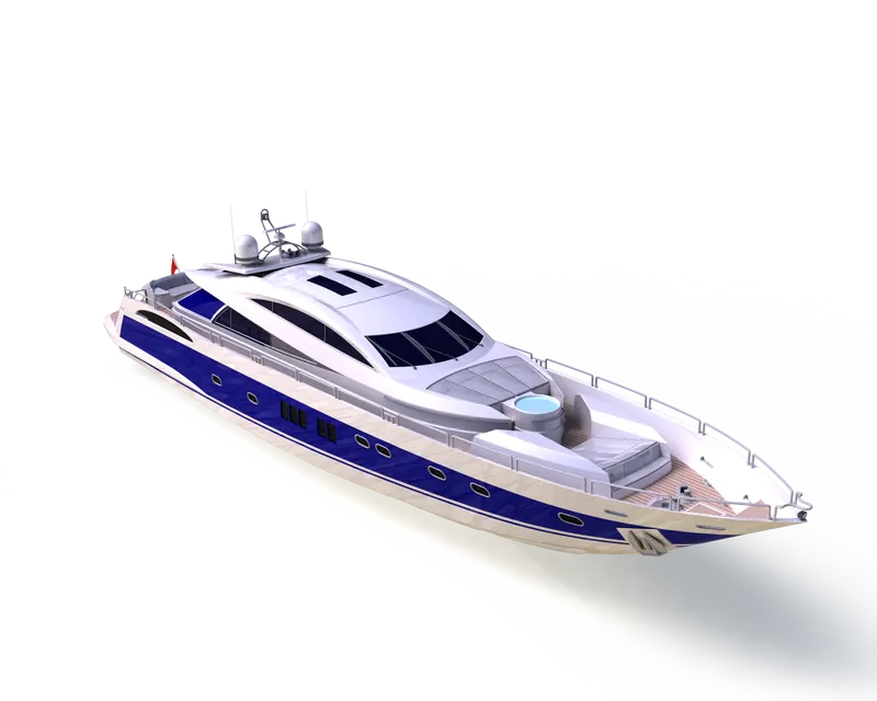
Rendering is done to apply real time graphics to the Yacht. We can assign a scene or environment in which the yacht is placed, and we can modify the colors or looks of it. We can use different like in Primary 360 View Rendering Images in different types of position
Conclusion:
Surface modelling is one of the complex things in designing. Selection appropriate tool to generate surfaces is key to modelling. The gaps between surfaces will play an important role while converting surface bodies into solid. This design of yacht will give an opportunity to explore the tools of surface modelling.