Week 8 - Challenge 3 - Switch Bezel Design
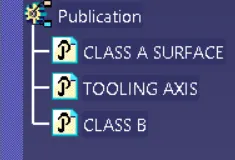
1. TREE STRUCTURE AND THE GEOMETRICAL SETS
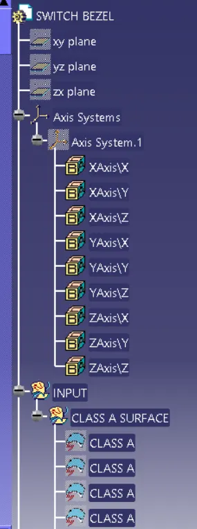
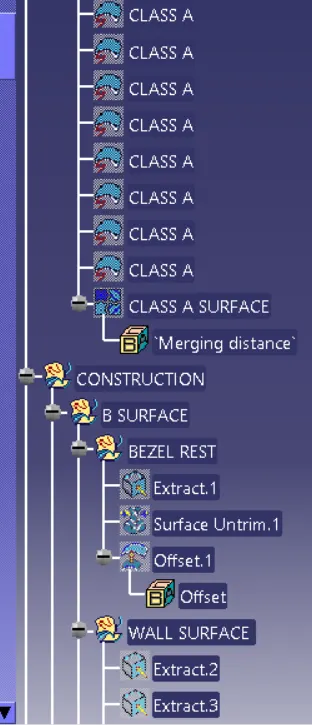
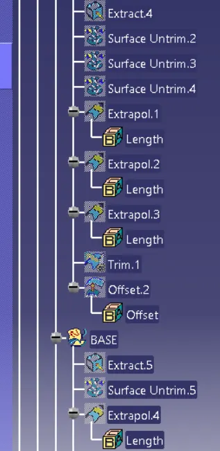
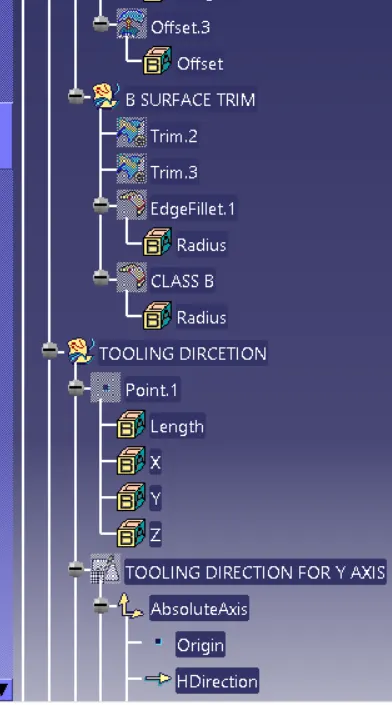
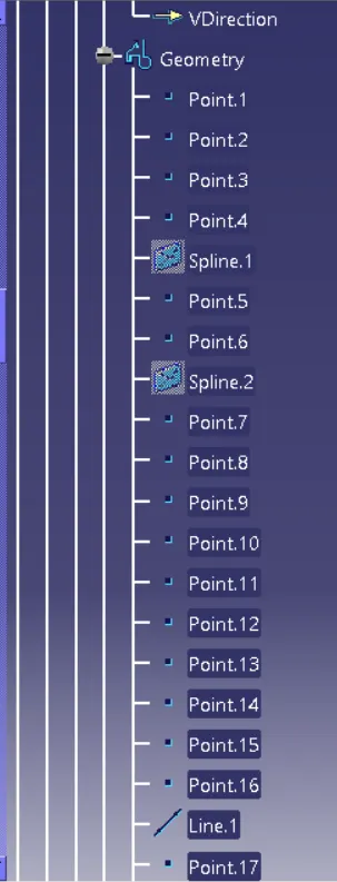
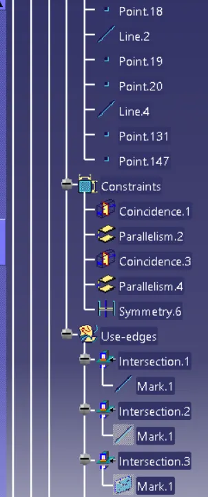
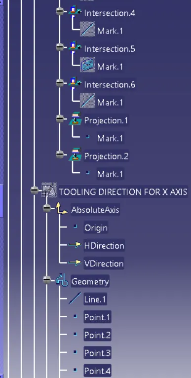
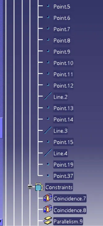
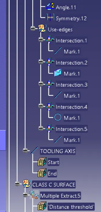
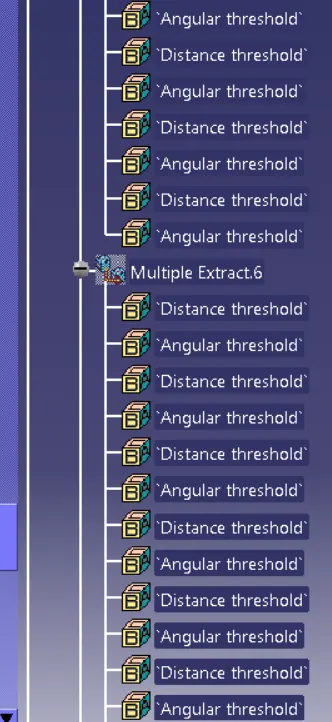
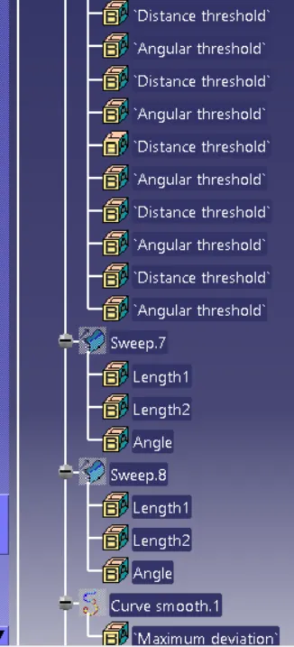
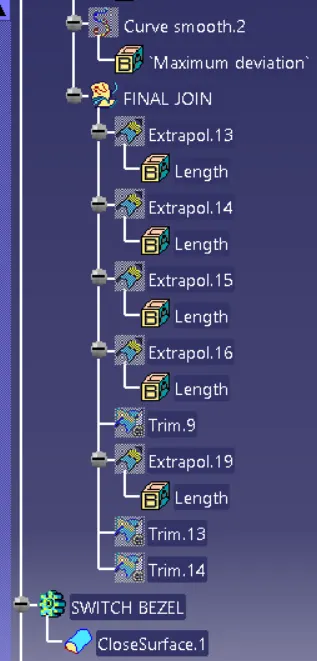
2. THE VARIOUS OREINTATION VIEW FOR THE SWITCH BEZEL
- FRONT VIEW
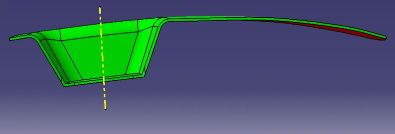
- SIDE VIEW
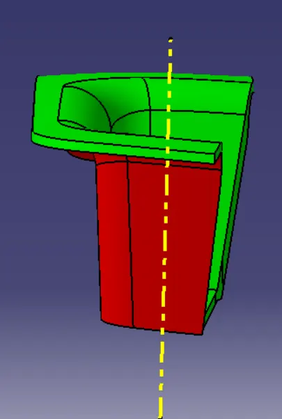
- TOP VIEW
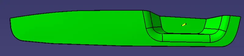
- ISOMETERIC VIEW
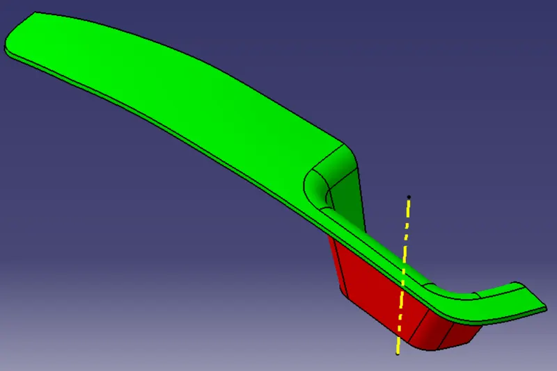
3. TOOLING AXIS
Create a point using base surface on the Class a Surface, after create a sketch,to create tooling line for X direction.
In first sketch intersect with the class a surface then create two line on the intersect curve and bisect the two line.
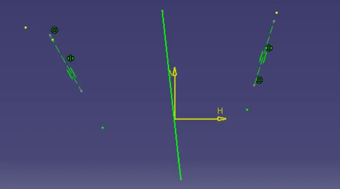
In sketch 2 create a intersect with the class A surface draw a line from the point give an anlge at minimun draft value after we can increase value.
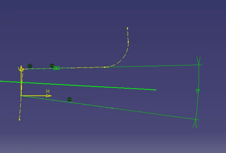
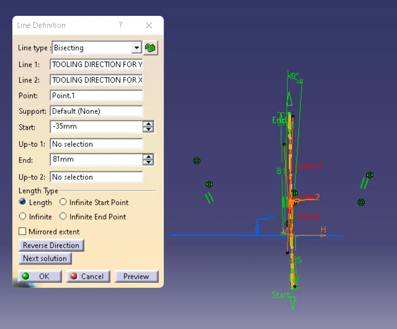
Bisect the sketch 1 and sketch 2 and form a Main Tooling Axis
4.CLASS SURFACE AND CLASS C SURFACE
- CLASS B SURFACE
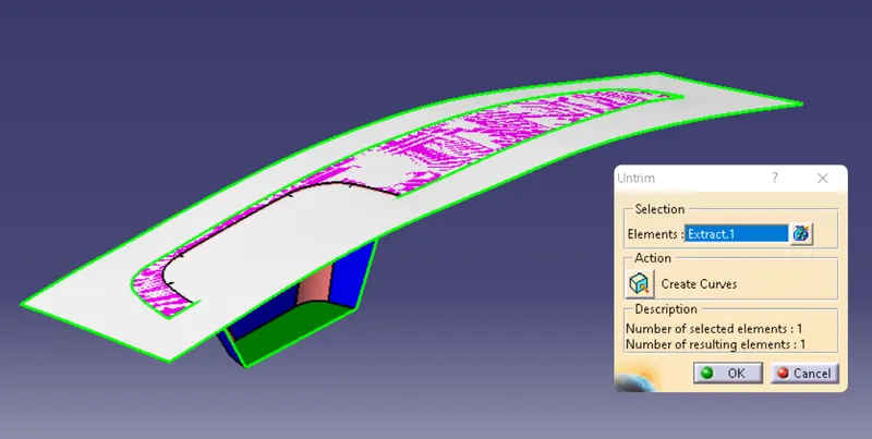
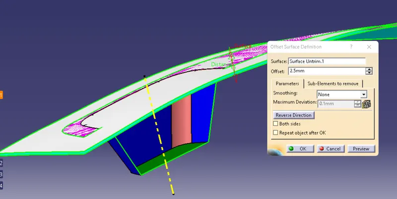
OFFSET AT 2.5MM
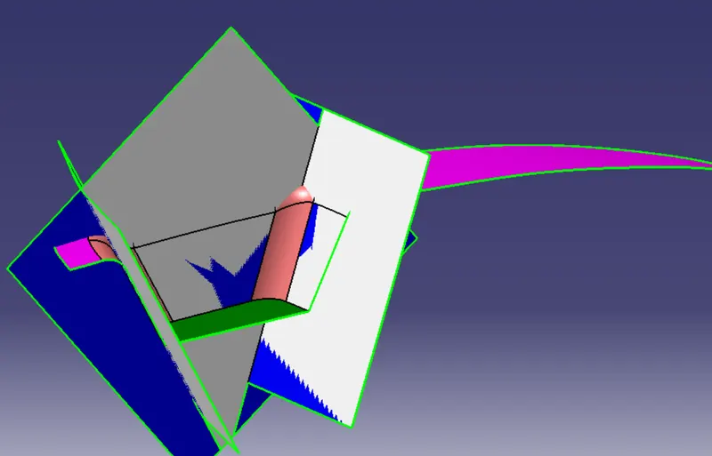
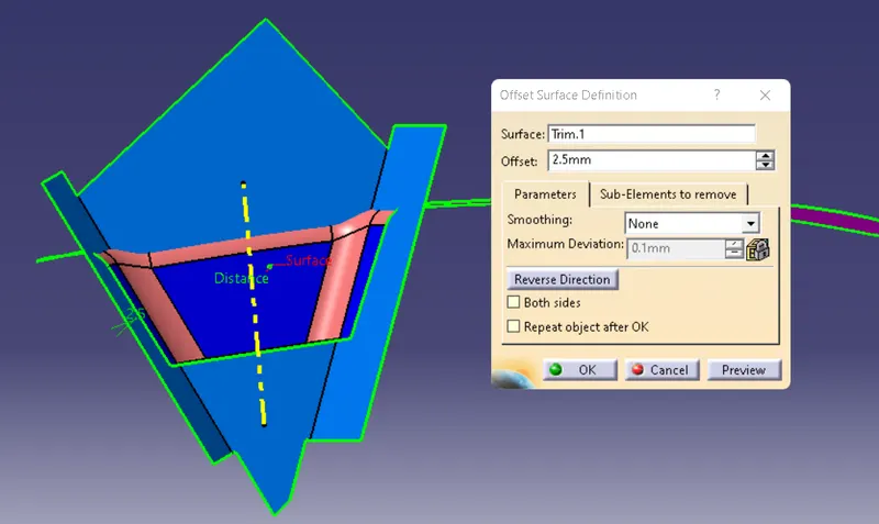
WALL SURFACE SHOULD OFFSET AT 2.5MM INWARD
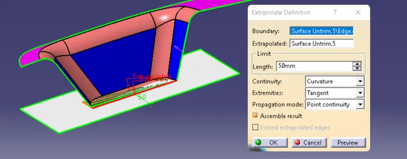
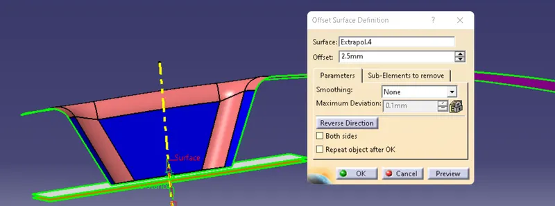
OFFSET WALL SURFACE AT 2.5MM
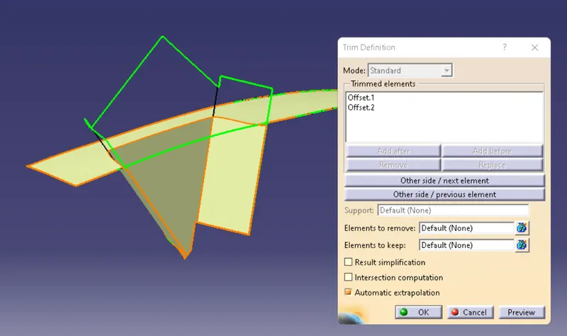
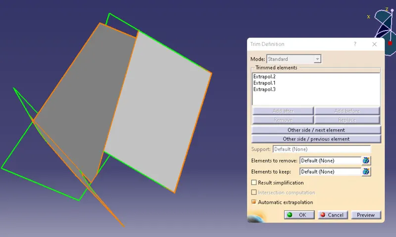
TRIM THE TOP SURFACE WITH WALL
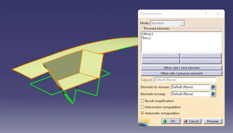
AFTER THAT TRIM AGAIN TRIM WITH THE BASE SURFACE AND ADD A FILLET TO THE TRIM
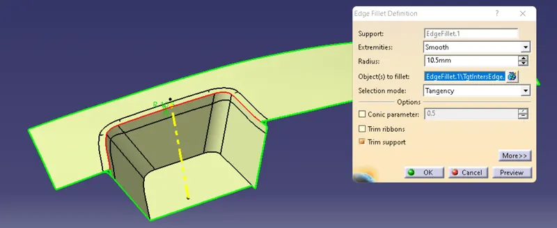
CLASS C SURFACE
Create a Multisurface boundary to the a Surface and use The Swept command to create a Class C Surface
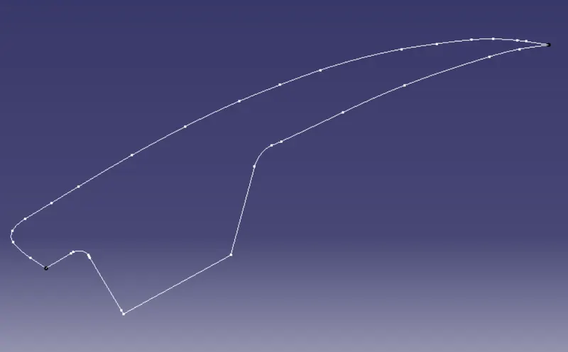
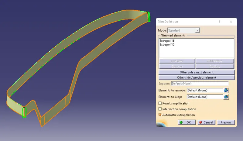
Trim the seep 1 and sweep 2 after that trim the Class C with Extraapolate Class A Surface.
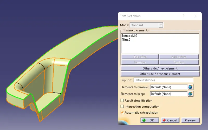
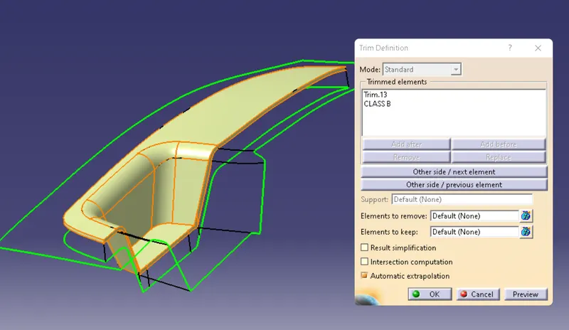
Final trim with Class C with Class B
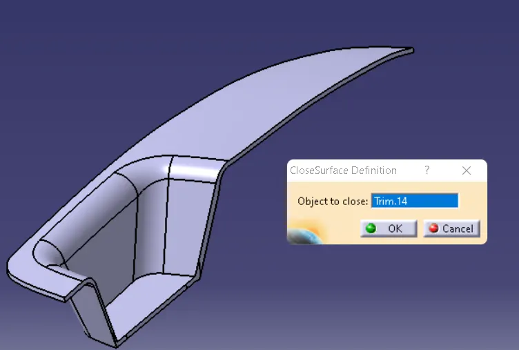
CLOSESURFACE BODY THICKNESS AT 2.5MM
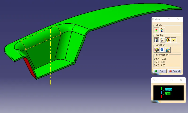
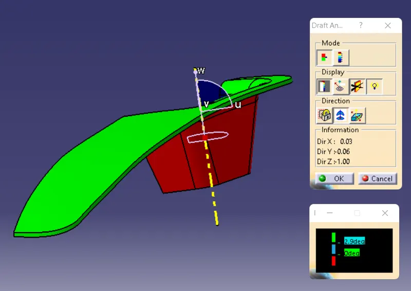
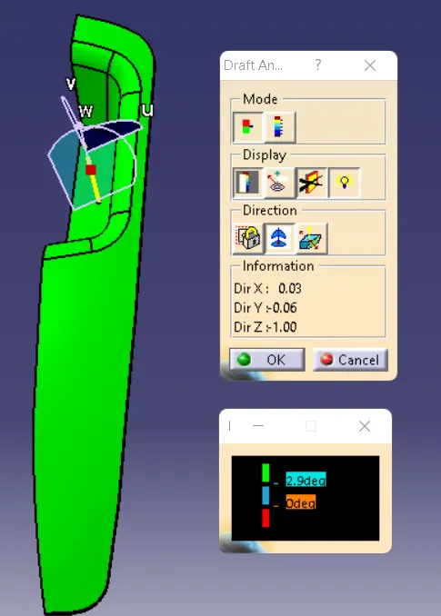
Draft Analysis for the Switch Bezel
The minimum draft angle should used in the draft is 2.9 degree
DETAILED REPORT :
Tooling Axis
First thing we should have analys which direction will be our Main tooling axis going to be.
then create tooling direction in the X direction and Y direction after Using Bisecting command bisecting the X and Y tooling line
then get the Main Tooling Aixs
Class B Surface
By using the Class A surface to Create the Class B surface first thing extract the top surface form class A,
Then untrim the surface and offset it at 2.5mm,
Then Create the wall for the switch bezel extract the surface from then untrim the surface and extrapolate it and trim offset at 2.5mm.
And create the base surface using clsass A, extract the base and untrim the surface trim offset at 2.5mm, trim all trim to create the B surface.
Class C Surface
Using the Multiple Extract at the boundary area for the Swept Surface Definition to create a C Surface.
The minimum swept angle is 3 degree , then trim the Class A surface with the Class C surface .
Finally Trim the Class B with Class C surface , check the final trim surface their would have any boundary or gaps on the surface
Make the complete surface using the closesurface body command select the final tirm to convert into close body.
Draft Analysis
Change the Material Mode to the Customize mode for the draft analysis pull the axis and place into the Main Tooling axis
and check draft on the soild body move curser and check the angle deviation on the body.
The Minimum draft should be in the draft analyasis is 3mm, but in our part we use 2.9 draft angle.