Week 8 - Challenge 2 - Base Bracket Design
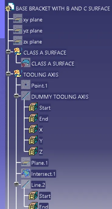
1. TREE STRUCTURE AND THE GEOMETRICAL SETS
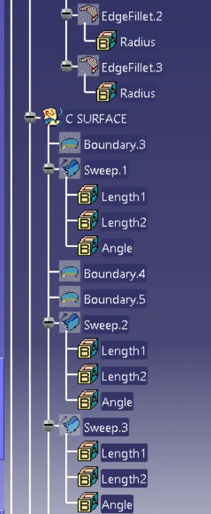
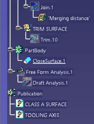
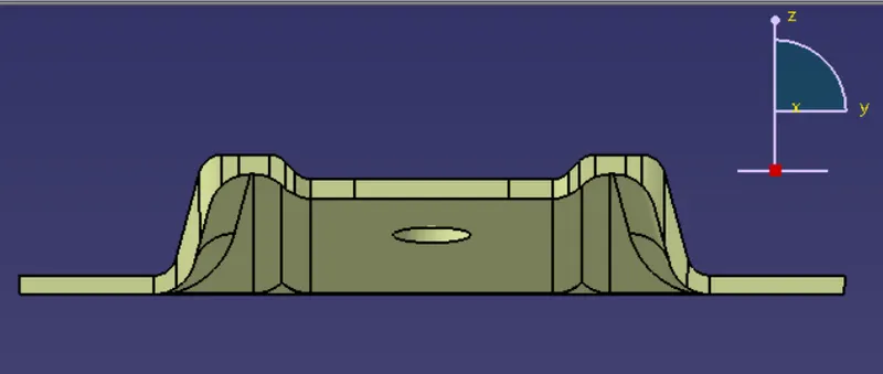
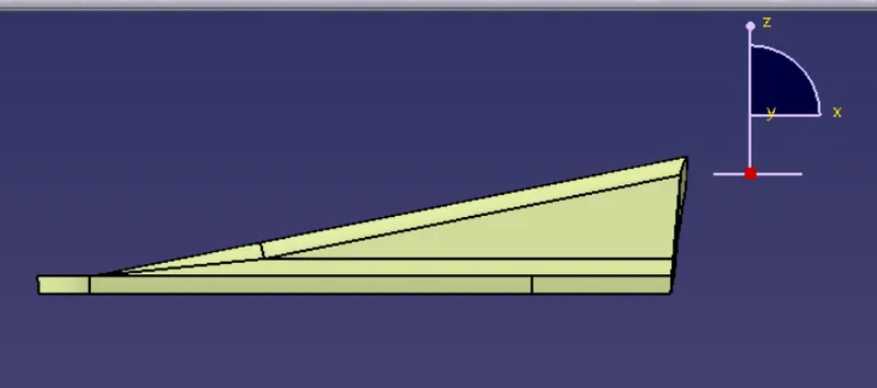
2. THE VARIOUS OREINTATION VIEW OF THE BASE BRACKET
- Front View
- Side View
- Top View
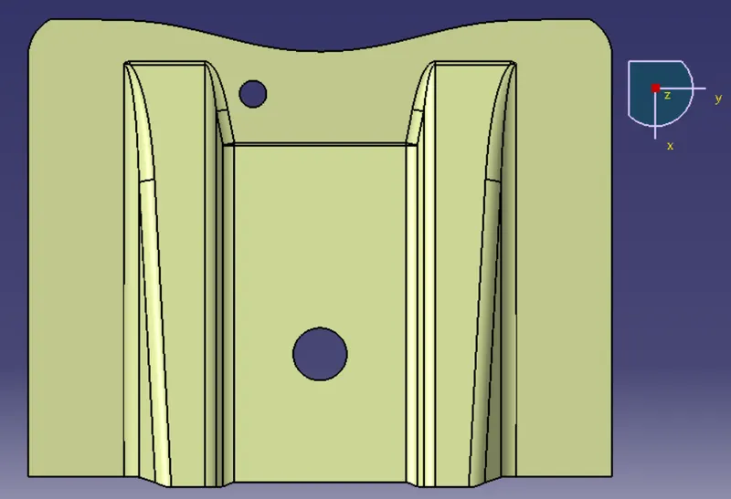
- Isometric View
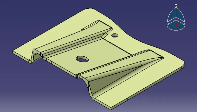
3.TOOLING AXIS
- Create a Point on the on the Class a Surface Point Type is Circle/Sphere, and Create one Plane by using Parallel through point and the Reference is YZ plane and select the Point.
- By using the Intersect command Create the intersec between the Plane one we created and the class A surface.
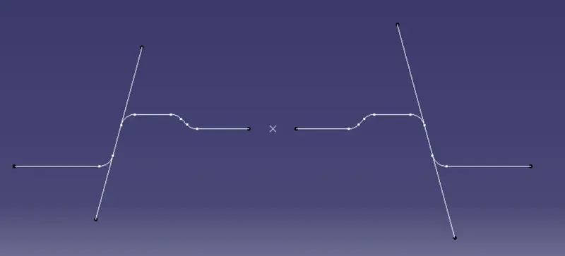
Using Bisecting Command for the Two Line to form a Main Tooling Axis
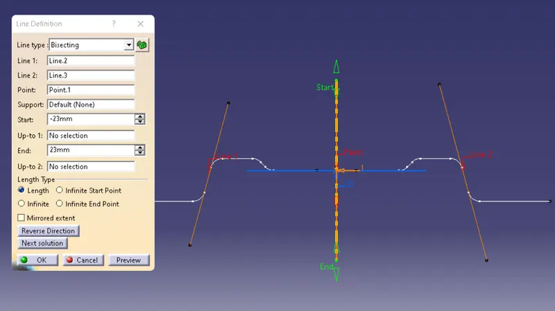
Main Tooling Aixs
4. CLASS B SURFACE AND CLASS C SURFACE
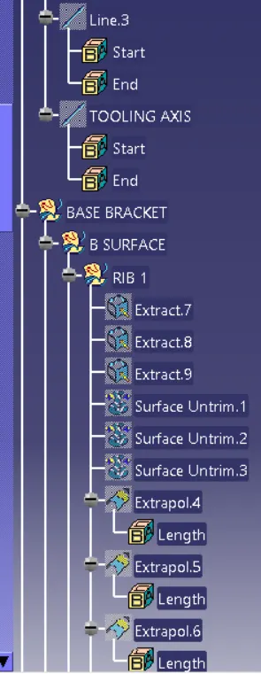
- B Surface
First we have to Create the B surface in that extract the Rib 1 first and untrim the surface than Extrapolate
after that trim the surface noe we got the Rib 1
Then Offset the trim surface at 2.5mm inward direction
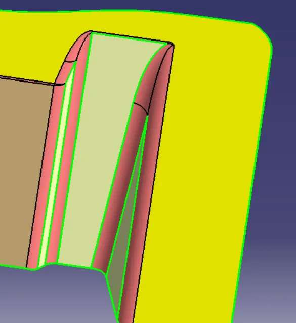
Extract Surface for Rib 1
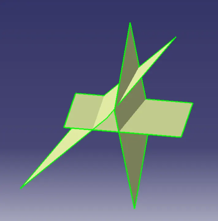
Extrapolate Surface for Rib 1
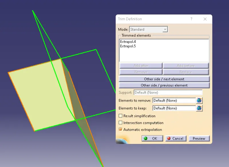
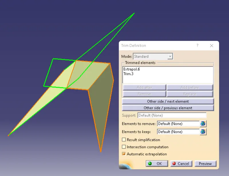 Trim surface
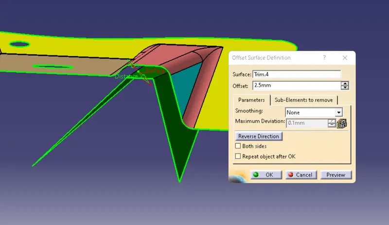
Offset 2.5mm at inward
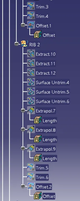
Again we can follow the same procedure for the othe side Rib 2 also, Extract the surface after untrim it and extrapolate it then Trim it and offset it at 2.5mm inward direction
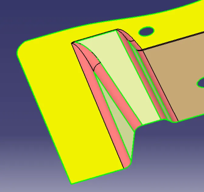
Extract surface of Rib 2
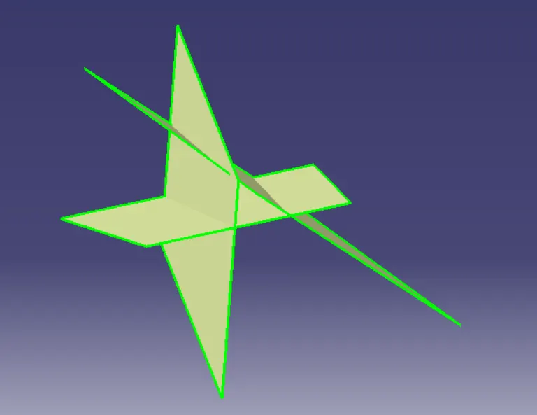
Extrapolate Surface of Rib 2
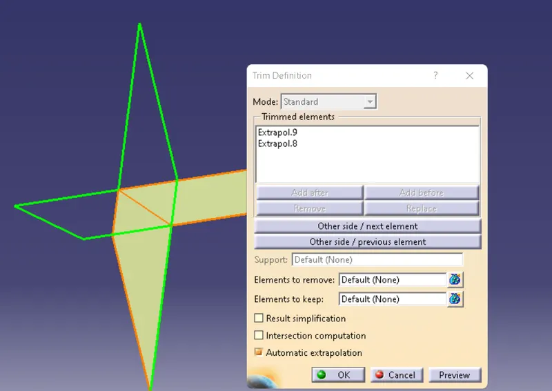
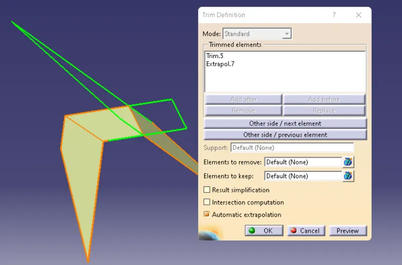
Trim the extrapolate surface
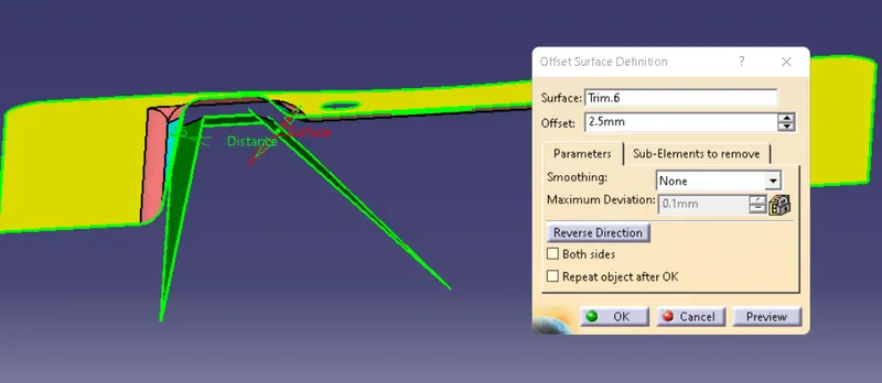
Offset the surface at 2.5mm inward
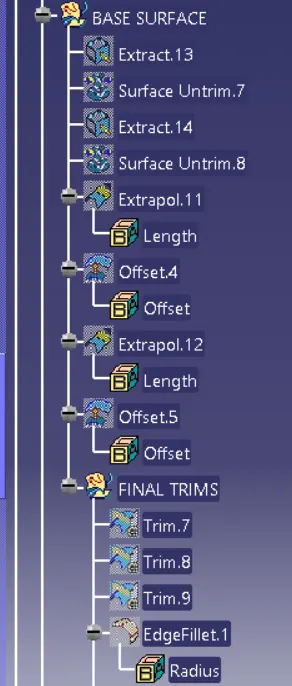
Now we Create the Base Surface for B surface
Extract the base surface from the Class A surface after Untrim the Extract Surface
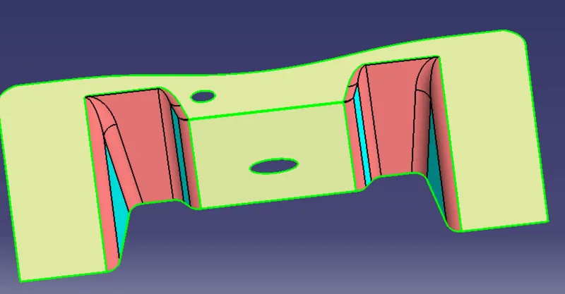
Extract surface from the Class A
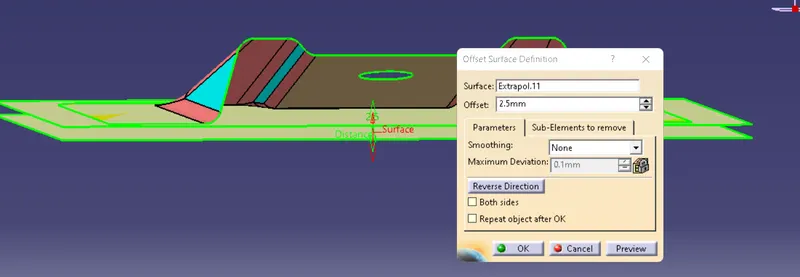
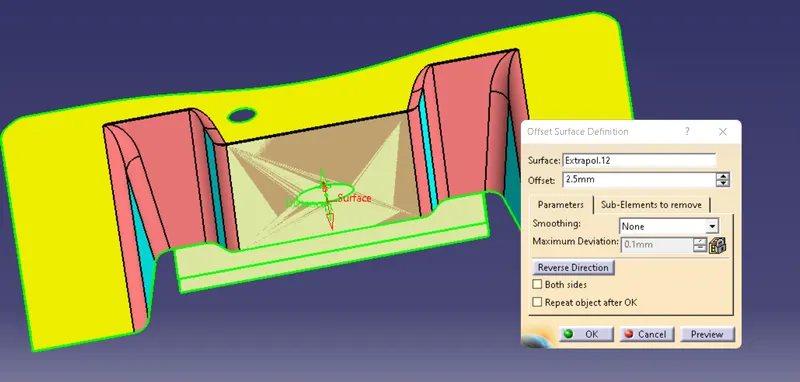
The Extrapolate Surface and Offset surface at 2.5mm inward direction
Final trim by usind the base surface and the Rib 1 and Rib 2
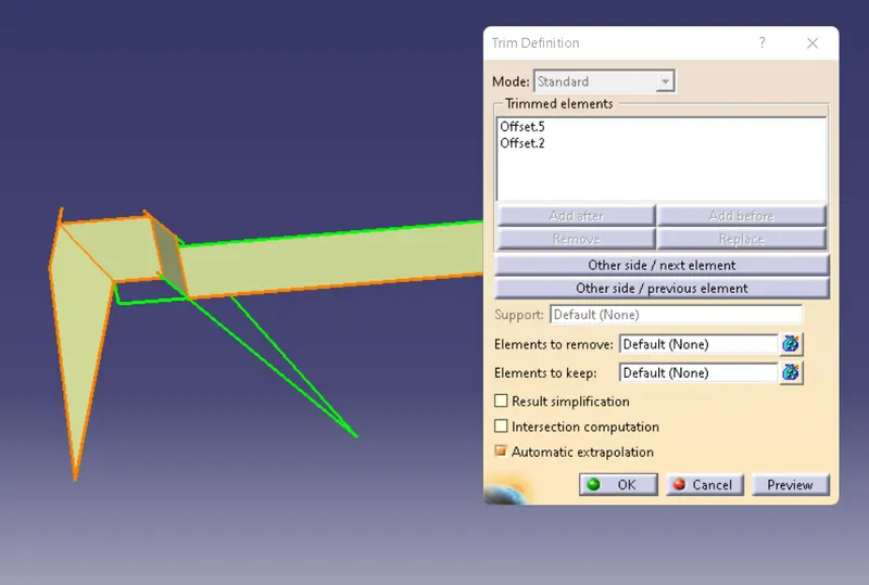
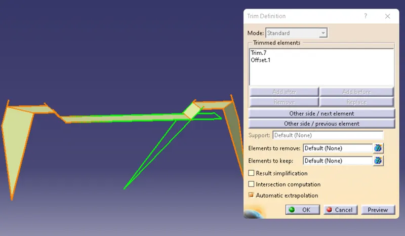
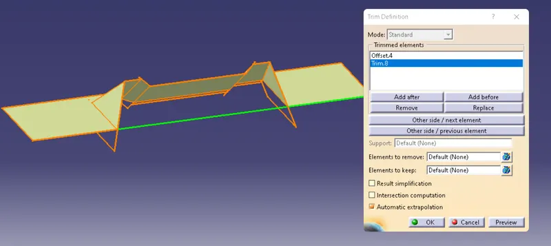
Final trim of the B surface
- C Surface
In the C Surface using a Boundary Command and Create the boundary on outer side and the Inner circle
after sweep the curve , Using Swept Surface Definition with the draft direction.
The minimum angle for the seep is 3 degree along the Tooling Axis For the direction
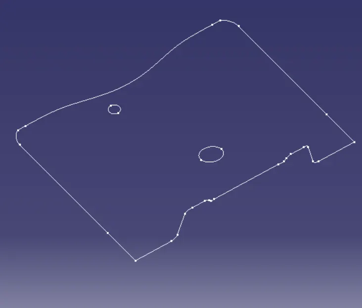
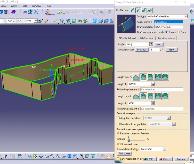
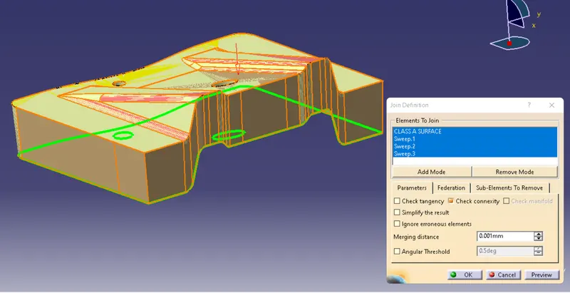
Joining the Class A Surface with the C Surface after Trim the Class C Surface with the Class B Surface
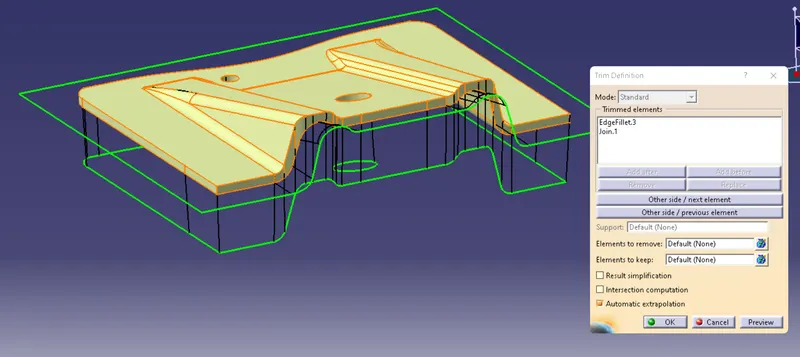
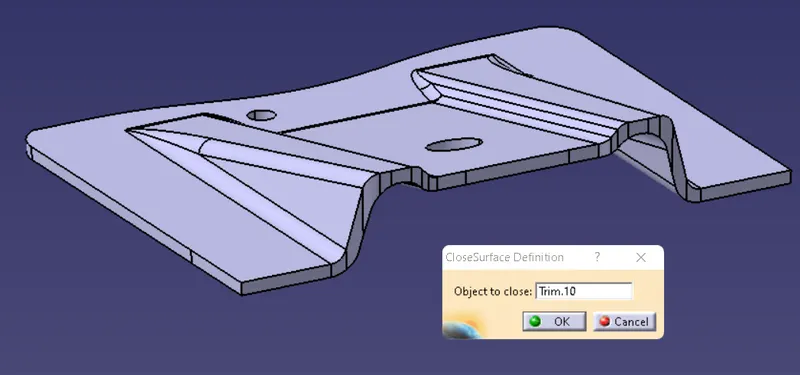
Check the Final Surface Their would have any caps or boundary on the surface if any caps it make error to form the closesurface body.
Now Change to the Part Design Select the Final Trim and use the Closesurface Body command then form and Body.
Draft Analysis For the Base Bracket
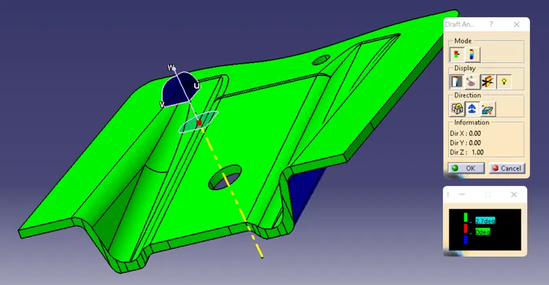
Here the Minimum Draft Angle is 2.7 degree
Insert- Analysis- Feature Draft Analysis
Pull the Direction and Place it into the Main tooling Axis check wheather any deviation in the draft then move curser to check the angle on it.