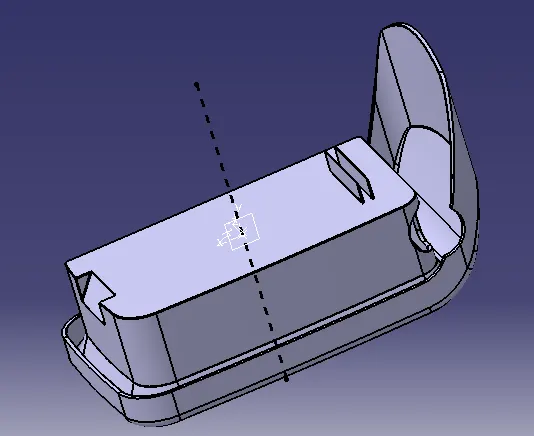
Week 9 - Attachment Feature Creation - Challenge 1
COIN HOLDER DESIGN
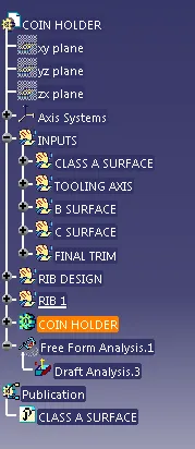
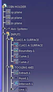
TREE STRUCTURE
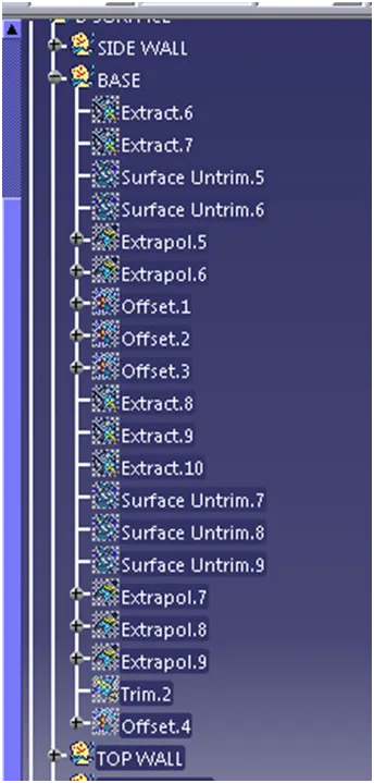
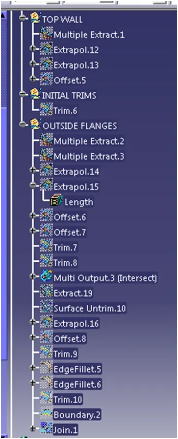
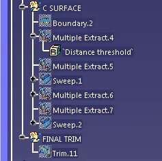
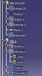
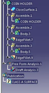
REPORT
INTRODUCTION
Using the class A surface of COIN HOLDER we are going to check the draft analysis and the tooling axis creation along with the class b and class c surface .
DRAFT ANALYSIS
Draft analysis is a method of checking the draft angle on various faces of a part with a particular direction.
The Draft Analysis command enables you to detect if the part you drafted will be easily removed. This type of analysis is performed based on color ranges identifying zones on the analyzed element where the deviation from the draft direction at any point, corresponds to specified values.
A draft angle is a slant that is applied to each side of most features of an injection molded part. The angle, which is positioned to run toward the direction of a mold's pull and parting line, helps with releasing the part from the mold.
TOOLING AXIS.
Tooling axis defines in which axis will be the most familiar and easy to process the draft analysis in the minimal way of operation taken in the molding die of the plastic component we required.
So from the class A surface checking the x,y&z plane of the output and clearing the all direction creating the tooling direction to perform the draft analysis without making any complication of taking out the component.
PROCEDURE
* Import the class A Surface into the CATIA workbench
* And check the class A surface is fully closed without any gap in the surface , using the JOIN and BOUNDARY option in the Generative shape design.
* After checking the surface of the class A is closed, check the possibility of the tooling axis in 3 axis x ,y , z.
*Tooling axis is the most important in the draft analysis.
* In the coin holder class A surface we checked the 3 axis, in that we preferred
the z axis is comfortable and easiest way of doing the draft analysis
*And in the Z axis too we have to check some of the consideration before creating the tooling axis.
* In this coin holder we cannot draft the class A surface to the tooling direction ,because the class A is parallel to the direction of Z axis in positive and negative side
* So we create the dummy tooling axis in Z axis on the base of the coin holder to perform the draft analysis.
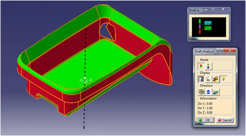
ISOMETRIC VIEW (UPWARD DRAFT DIRECTION)
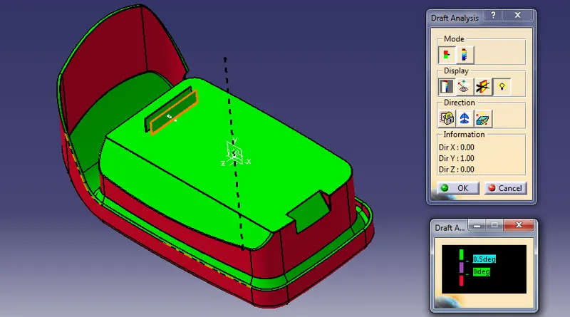
ISOMETRIC VIEW (DOWNWARD DRAFT DIRECTION)
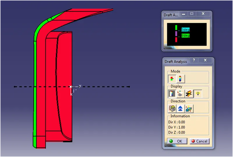
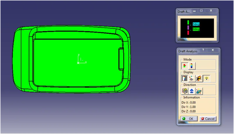
*At initial class A surface is failing in the Draft angle, so in Class A of the coin holder the Red colour highlighted area to be redesigned according to clear the draft angle of 3 deg.
* So that the plastic components of the coin holder can be done without any defects in the red highlighted area as mentioned in upward draft direction.
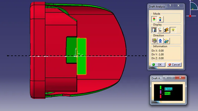
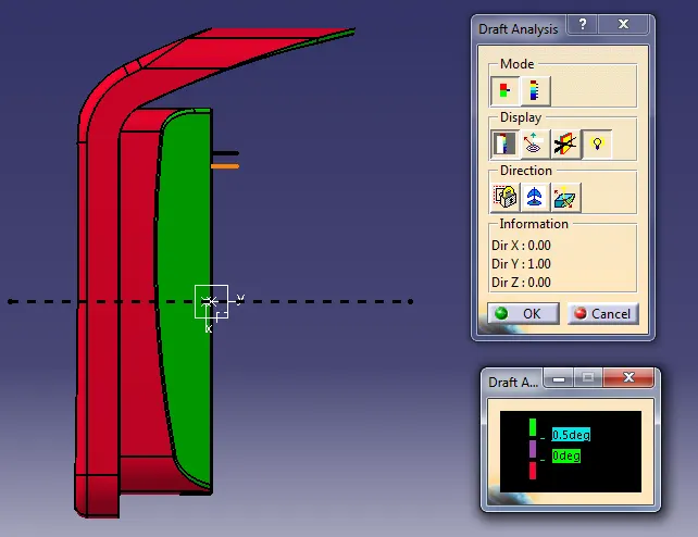
*For ribs we have checked the downward draft at draft deg of 0.5 deg.
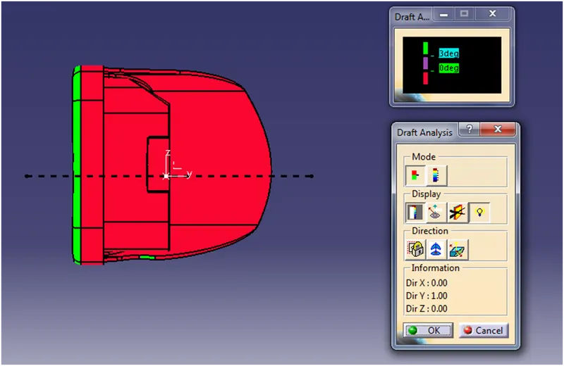
FRONT VIEW (UPWARD DRAFT DIRECTION)
FRONT VIEW (DOWNWARD DRAFT DIRECTION)
SIDE VIEW (UPWARD DRAFT DIRECTION)
SIDE VIEW (DOWNWARD DRAFT DIRECTION)
TOP VIEW (UPWARD DRAFT DIRECTION)
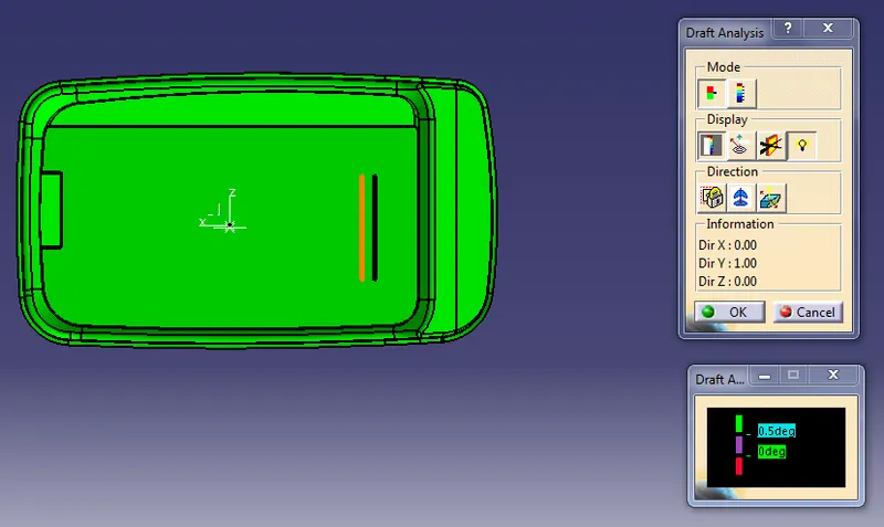
TOP VIEW (DOWNWARD DRAFT DIRECTION)
CLASS B SURFACE
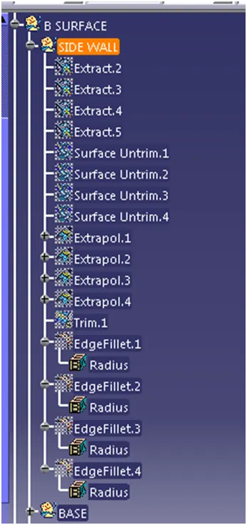
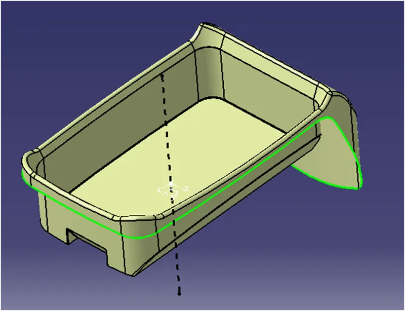
*In the COIN HOLDER we have separated the top, side walls and the base part as three sub portion from the class A surface.
*Extract the class A surface into different parts and untrim the required portion, if needed extrapolate the untrim portion and finally trim the required portion of the class A.
*And offset to the thickness of 2.5mm the final trimmed portion we got the class B surface .
CLASS C SURFACE
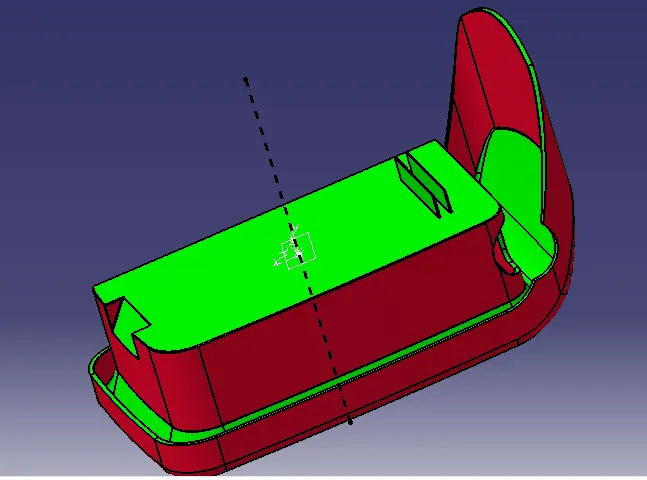
*From the class A surface extract the boundary from it and using the sweep option , from the profile type and with reference to the surface .
*Extract the outer surface from the class A ,using the boundary and the reference surface create the C surface .
*And trim the B surface and the sweep surface and join with the class A surface ,we got the C surface .
*Final output we will get as the closed coin holder surface part and using part design make it like the closed surface.
*And extract the boundary of the cuts portion from the class A, and sweep the cut portion and trim with the main surface.
RIBS CREATION
*Sketch on the bottom extract surface from the final coin holder, and extrude the surface.
*The wall thickness of the components T=2.5mm
*And thinken the surface using the part workbench for the value of 0.4xT (Thickness of the wall) ,and draft the edges of the thicken surface at 0.5 deg as per the standard of rib design 0.125xT
*And check the height of the ribs 5xT, along with the rib tip is greater than 0.75mm
*Make the rib edges fillet value of 0.25 mm MAX .
* And create the plane and intersect the coin holder with rib.
*From the intersection sketch we can check the rib root thickness ,it should be 30 percentage above or below to the wall thickness.
*We checking the root thickness of the ribs to prevent shrinkage of the components from the defect.
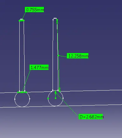
*And similarly copy the sketch follow the same steps ,but distance to be the 2xT from the existing rib.
*These are the steps to be followed in the rib creating of the plastic components
CONCLUSION.
At last using the Class A surface we have done the Draft analysis ,and for draft analysis we created the tooling axis . Also we have created the B surface and C surface to make the coin holder plastic modeling, along with the rib design and standards followed in the industrial practice