Aston Martin ONE-77 Challenge-11 (Project)
TITLE OF PROJECT
SURFACE AND SOLID MODELING OF ASTON MARTIN ONE 77 ALONG WITH ASSEMBLY AND RENDERING USING SOLIDWORKS
OBJECTIVE
- The main objective of this project is to model a ASTON MARTIN ONE 77 by solidworks in solid and surface modelling environment.
- Assemble the designed parts by using a solidworks Assemble environment.
- To create a photo-realistic view of ASTON MARTIN ONE 77 by rendering the model using solidworks photo view 360 and solidworks visualize.
INTRODUCTION
- The Aston Martin One-77 is a two-door, two-seater flagship sports car built by the British car manufacturer Aston Martin.
- The car was first shown at the 2008 Paris Motor Show, although it remained mostly covered by a "Savile Row tailored skirt" throughout the show.
|
Manufacturer |
Aston Martin Lagonda Limited |
|
Production |
2009–2012 |
|
Model years |
2009–2012 |
|
Assembly |
United Kingdom: : Gaydon,warwickshire |
|
Designer |
Marek Reichman |
| Dimensions | |
|---|---|
| Wheelbase | 2,791 mm |
| Length | 4,601 mm |
| Width | 2,204 mm |
| Height | 1,222 mm |
| Kerb weight | 1,630 kg |
The above general details gives the model we going to replica and below upcoming gives you the designing methodology and approaches we used to do the part model of the ASTON MARTIN ONE 77 .
DESIGN METHODOLOGY & DESCRIPTION
The flow charts gives you the design methodology of part modelling and the Assembly of the ASTON MARTIN ONE 77.
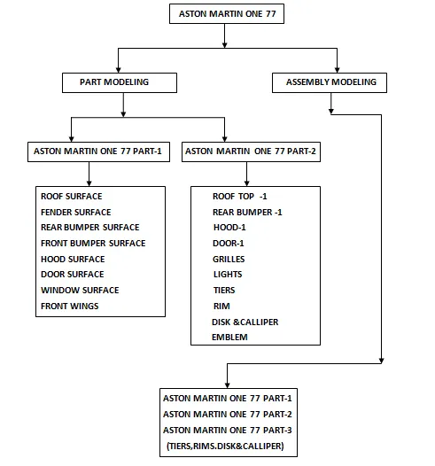
Now we are going to see the approaches in solidworks to create the part modelling of ASTON MARTIN ONE 77 in sequence.
1. BLUEPRINTS SETUPS:
- Open the new part model in the software, save the file name as ASTON MARTIN ONE 77 and next to that the main things is to set the units for the model in the DOCUMENT PROPERTIES>UNITS>CGS .
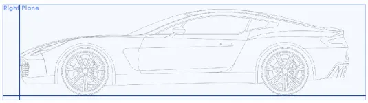
- Start selecting the planes and click edit sketch TOOLS>SKETCH TOOLS>SKETCH PICTURE and inserted the front, side ,top and rear view of the blueprints in the respective plane with correct dimensions as per study material and exit sketch to view that blueprints.
- The blueprints is the basic step or reference for the whole modelling so that we can create a model in the perfect and accurate way to outcome.
- For reference the below side view blueprints is shown below PIC.1,similarly other views will be as follows
PIC.1
Next we move to the part modelling of the ASTON MARTIN ONE 77
2.PART MODELING:
- In the main component they are sub divided into many small parts ,we cant able to design the component in the single part ,so we are splitting that into small parts and finally combined into single assembly.
- Let we consider in the ASTON MARTIN ONE 77 we are splitting the outer body of the car into many parts as mentioned above in the design methodology earlier.
- We are going to see the parts in sequence one by one as mentioned in the design methodology .
a) Roof Surface
An automobile roof or car top is the portion of an automobile that sits above the passenger compartment, protecting the vehicle occupants from sun, wind, rain, and other external elements.
- First step is to create the 2D sketches in the respective plane as shown in the study material by Side plane>sketch icon in the popup .
- For sketching use the following sketch ribbon tools for creating the roof surface
- Two point Splines, Three point splines lines, reference lines sketch tool help to make the roof surface.
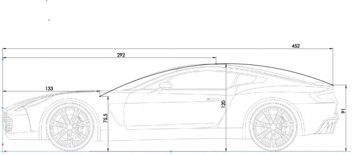
- After sketched use smart dimensions for the exact length or required dimensions for fully constraints the sketch from the origin as shown below PIC.2.The black colour of the sketches indicated it is fully defined, each and every sketches to be fully defined, it is a important note in modelling.
PIC.2
- After the 2D sketches we are going to create the Projected curve by Insert>Curve>Projected Curve.
- Projected curve can be constructed using two sketches of perpendicular plane .
- Also create the planes offset from the front plane for suitable 2D profile creation by,Features>Reference geometry>Plane.
- Like similiarly select the other 2D profiles too in the study material and created the 3D Curve.
- You get the closed profile of the roof and just started creating the extuded surface of the roof.
- Surface>Boundary surface, Select the last two outer curve in the direction 1 and intermediate sketch for the smoothness of the surface.
- And each curve select the direction vector like normal to profile or direction vector or none, as in the study material and validate.
- you get the roof surface, in these model, we are going to create the one side of the model and finally we mirror the other side for easy finishing of the model.
b) Fender surface.
Fender is the American English term for the part of an automobile, motorcycle or other vehicle body that frames a wheel well (the fender underside). Its primary purpose is to prevent sand, mud, rocks, liquids, and other road spray from being thrown into the air by the rotating tire. Fenders are typically rigid and can be damaged by contact with the road surface.
- The front fender tip is created as per the study material and the below tools mentioned .
- As previously said in the roof surface the same procedure is using here regarding sketching the 2D profile along with smart dimensions, constraints, fully defined, projected curves, and surface extrude as same follows.
- In addition we using some more features for fenders surface like circle tool and offset of the 2D sketch
- And trim entities we are using it newly for creating the fender surface, the trim tool helps to cut the unwanted surface from the extruded surface with matched the 2D profile we created.
- You can find the trim tool from Insert>Surface>Trim .
- Like same procedure for the front fender tip the back side of the fender tip is also created.
- And after that front and back fender tip, the connecting surface of the front and back fender tip is going to create .
- The sketch for the inter between portion should connect and fully constraints with the front and back fender tip ,so that we can be easily able to extrude the surface or else we will face error in that.
- so while sketching the 2D profile we should constraint and fully defined the 2D sketch .
- And in the surface extrude we are going to add some more options, while selecting the outer profile in direction box ,the tangency to be ticked because it match to previous surface and click the merge too so that newly extruded tangency face and the inter between portion merge with both fender tips.
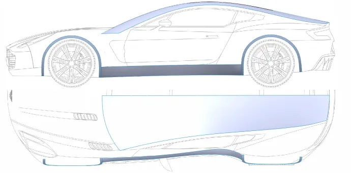
- The below PIC.3 shows the created surface in the fender portion
PIC.3
c) Door & fender surface.
A car door is a type of door, typically hinged, but sometimes attached by other mechanisms such as tracks, in front of an opening which is used for entering and exiting a vehicle. A vehicle door can be opened to provide access to the opening, or closed to secure it. These doors can be opened manually, or powered electronically.
- As previously said in the roof surface the same procedure is using here regarding sketching the 2D profile along with smart dimensions, constraints, fully defined, projected curves, and surface extrude as same follows.
- Convert entities is the new features using here to create the door extruded surface ,the convert entities is mainly used for referring the previous sketch or projected curve that not to create one more time the same profile.
- And in the extruded surface we are adding one more option along with merge tangency faces the trim by direction 2 is added to that tool..
- The trim with direction is used to trim the extended surface to the required surface we need, the direction help to which side need to be trimmed .
- Now we can see the door surface we want in the below PIC.4
- After this in-beteween area fender and door surface is going to create
- The in-between area of fender and door surface cant be created into single surface due to tangency and smoothness profile of the surface.
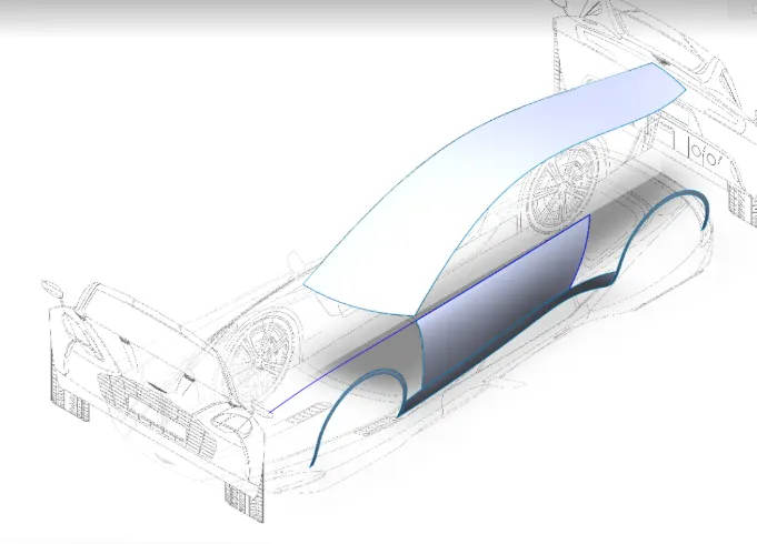
PIC.4
- For creating that surface we need to create the planes offset from the front plane at the distance of 56,92 &115 distance.
- Start sketch on the each plane and the sketch that have pierce relation with the previous 3D curve and the fender portion, like similarly sketch on the other two plane.
- Additionally one more Horizontal plane at the distance of 56 is created and sketch with pierce relation like previously said and exit the sketch.
- Use intersection curve from convert entities it helps us to connect the door surface and the fender in the previous sketch.
- Create Boundary surface with the sketch and trim the required portion by trim by direction1 & direction 2.
- Like pervious said for boundary surface the tangency portion can be selected by right click in the direction box>selection manager tool is used .
- It will create like open loop in direction 1 and select the other side for closed boundary surface so that the boundary surface is extruded.
- One part of the surface is created in-between the fender and door.
- We already created the sketches for the need of other two tiny surface.
- New tool we are going to see Fill surface from Insert>surface.
- Select the 5 edges and select the Fix up boundaries in the options below in fill surface also select the face option it will help the surface that match the previous surface and validate it.
- Now another new tool is Knit surface is used for combine all the previous surface show like one single surface. This tool we will use frequently throughout the model completion.
- Like similarly the back side of the door and fender in-between portion is created as above.
- For creating that one more additional surface above that created 1st and then the in-between portion of back side door and back fender can be created.
- Same procedure like sketch ,boundary surface extrude ,fill surface and pierce relation as follows in the study material.
- And Knit the surface finally to combine as single surface as shown below PIC.5
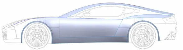
PIC.5
d) Rear Bumper surface.
Rear surface is the back portion of the car it includes the bumper, tail light, back door, name plate of the car, like every portion of the car the back is also a one of the unique part of the car gives you the elegant look for the car.
- Start sketch on the side and top plane and respectively, and create the projected curve using two perpendicular plane.
- Creating that surface we need to create the planes in top and right respectively given in the study material .
- Pierce is the constraints we use typically in the 2D profiles that connect the pervious surface and related projected curves.
- Use the sketch make the boundary surface, use the normal to the profile option in the boundary surface to make the extruded surface of the rear one portion.
- Again Creating that surface we need to create the planes in front as per given in the study material.
- And do the same procedure as instructed in the study material as done early.
- In one portion of the rear surface we will create the plane in the new way that Insert>Reference Geometry>plane by selecting the line as 1st reference and the plane as 2nd reference so that the pane will come accordingly to both reference.
- And in few sketches we use the model outline as a wireframe structure so that we can be able see visible layer of the extruded surface.
- In Few surface creating, filled surface tool is used instead of apply all edges option, we using optimize surface and in the constrains curves selecting the intermediate sketch for better finishing surface and profile that we need to get in the surface output.
- At finishing all the splitted surface portion in the rear bumper use the Knit tool to combine that to a single portion i will help in the later part of the surface modelling as shown in the PIC.6
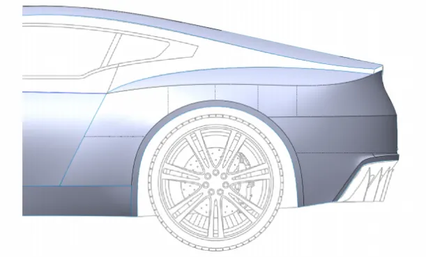
PIC.6
- After creating the rear surface portion of the ASTON MARTIN ON 77,now we are going to use some of the new tools which we don't use previously .
- The surface offset is the tool going to see 1st by clicking Insert>Surface>Offset, this tools helps us to offset the surface we want ,in that offset surface we will use make some new features without disturbing the original surface and also giving distance to the offset surface .
- Next tool is Insert>Face>Delete, in that select the face that we want to remove, for eg. the offset surface we created earlier. Two layer is overlapped each other for the need and purpose we can delete the one of the surface we want.
- In that there is 3 options below Delete, Delete and patch, Delete and fill, for the need and our convenience for the surface we can use the 3 above optionand use one of it.
- Insert>Surface>Ruled Surface is the another tool in the surface creation, it will helps to make the thin sheet surface by selecting the edges of the surface .
- In the ruled surface many option are below for the creating thin sheet surface of the selected edge as follows, Tangency to surface, Normal to surface, Tangency to vector, Perpendicular to vector, Sweep.
- And the ruled surface which obeys to the plane of selection in direction, and below that trim and knit helps to required shape and profile we selected as per the ruled surface will create and it is knitted together
- We can select the 2 or more edges for the ruled surface if we tick the Connecting surface it will replica as a single ruled surface .
- Insert>Surface>Fillet tools is similarly to sketch fillet but in the surface we are fillet the sharp edges to the required radius.
- As per step by step instructed in the study material we can finally see the rear surface of the ASTON MARTIN ONE 77 in below PIC.7
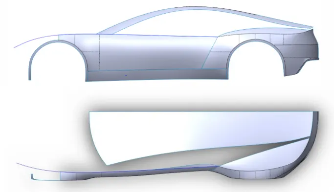
PIC .7
d) Front Bumper surface.
A bumper is a structure attached to or integrated with the front ends of a motor vehicle, to absorb impact in a minor collision, ideally minimizing repair costs. Numerous developments, improvements in materials and technologies, as well as greater focus on functionality for protecting vehicle components and improving safety have changed bumpers over the years. The front bumper is like the face of the car and most important one.
- Like every surface modelling, starting with sketches as per the study material given, and extruded the surface .
- Insert>Surface>Move/Copy now we are going to see, its helps to move or copy the created extruded surface at the position we need to move or copy, it is similar to the offset the surface but in offset we cant move to any extend in all the direction . But here we can move in all the direction as we required.
- Make note that while creating the sketches try to do constraints with the origin and the main planes, so that while if any changes occurs in some pervious sketch or surface ,it wont affect the your current or some previous sketches.
- It will create a big issues while creating a big file with lots of small tiny portion of the part.
- 3D sketches also can be created for the additional guides for the surface creation mostly 3D sketches can be created in the complicated profiles of 2D sketches.
- Insert>Surface>Fillet round tool is used for making the two surface of adjacent sides with different profile, in that profile make the both sharp connecting edge surface with smooth and tangency.
- Before fillet the two surface the both adjacent surface to be Knit together then only it can filleted.
- In the fillet round we have more option for doing the fillet to the surface that we see later upcoming profile.
- Insert>Surface>Extend tool is used to extend the extrude surface at the required distance according to the path of the surface.
- And while sketching we can also move and copy, scale, rotate, stretch the entities in the features pallet.
- In the below option we can see the From/To by clicking the start point and the end point you can move the entities.
- Insert>Bose base>Thickness tools is used to give additional thickness to the surface, these tool is used is some of the bottom surface of the bumper.
- After creating the thickness you see in the tree top of the solid bodies, by clicking the solid bodies under the solid bodies the surface we can find.
- Like similarly you can able to see the extruded surface in the below surface bodies in the top of the tree.
- Insert>Features>Split tool is used split the extruded surface into the 2 or 3 surface as per sketch created above the extruded surface.
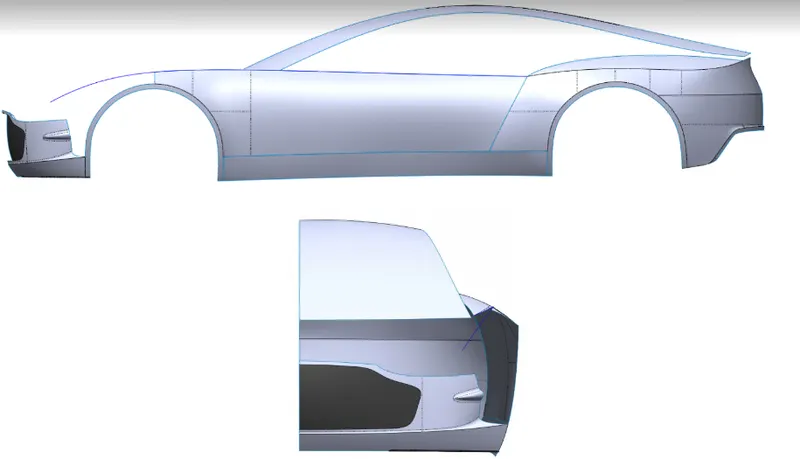
- Sketches plays a major role in the splitting the surface and follow the procedure step by step we can see the output of front bumper below like this PIC.8
PIC.8
e) Hood and Roof surface.
A car hood, also referred to as a bonnet in some other countries, is the hinged cover that rests over the engine of a front-engine vehicle. Its purpose is to provide access to the engine for repair and maintenance. Car hoods are typically constructed from steel and sometimes from aluminium.
- Before starting the hood portion we are going to give a additional profile to split the earlier roof surface that we extruded from the profile we need.
- By split the roof as similar procedure we explained in the before splitting of extruded surface .
- And now coming to hood surface ,it is a typical steps like sketch the profile need, projected 3D Curves is created using sketches and using the 3D curves extrude the surface with the closed boundary as mentioned earlier.
- Split option is also using in the hood surface to give additional features that to be used after.
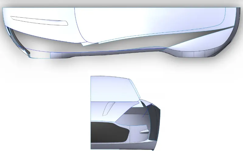
- After split, trim is used to cut the splitted surface and for that trimmed surface gap ,using the fill surface option to fill the gap surface according to the study material and profile needed as shown in PIC.9.
PIC .9
e) Window surface.
Vehicle glass includes windscreens, side and rear windows, and glass panel roofs on a vehicle. Back Glass also called rear window glass, rear windshield, or rear glass, is the piece of glass opposite the windshield in a vehicle
- For creating the window surface , we have create the outer surface of the window, in the software we are mostly creating all the profiles in the surface user environment only.
- According to the need we are changing the appearance for the surface and the material properties we are defining to it.
- For windows we are changing it properties as glass and appearances as transparency.
- Creating the window surface we need more plane according to the profile creation.
- Small-Small portion of the outer surface is creating on by on as follows in the study material.
- The typical steps like sketch the profile need, projected 3D Curves is created using sketches and using the 3D curves extrude the surface with the closed boundary as mentioned earlier.
- In the critical portion create few 3D sketches for closed loop and extrude the surface.
- After creating all the outer portion of the window use Knit command to knit all those surface .
- Now you got the closed surface of the window, by making some extra profile you can easily build the window surface .
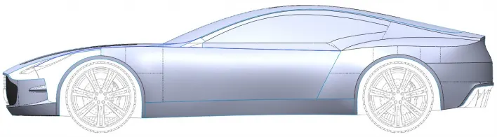
- Fillet the sharp edges of the window at required portion as per the study material and the windows will project as below PIC.10
PIC.10
f) Door surface.
- At first we created the outer body surface above but now we are going give additional features for the door.
- Draw the needed profile we need to give the special features for door and trim the surface from the extruded surface.
- Create the sketches as follows in the study material and form the projected curve and the extrude the closed profile of the door surface.
- The extruded surface is slightly offseted inside the trimmed surface at the front side of the door.
- Next upcoming profiles are little different from the before all the profiles we seen till now.
- But all the tools that we used little familiarly in the above all profiles.
- The ways of sketches will be different from the above all, so follow the study material keenly and do it or else we will face some errors in creating surface .
- we cant explain each and every steps in one by one as per given.
- Now one features we are going to see that is Isolate, it helps to separate the surface from the other surface and show alone the surfcae we want in the model environment.
- it will helps to give more extra attention in that surface creating, some sketches are more difficult to create for that profile we use isolate option.
- After creating the needed profile we can exit isolate surface.
- And we will create the inclined intersection extrude surface for the need of the model, trim the unwanted surface.
- Fillet command is used to give the radius of the profile at sharp edges.
- Insert>Face>Delete Tool is used to delete the face of the extruded surface, the face is deleted because with the outer profile we can give more special surface extrude to the deleted face.
- Fill, covert entities , surface fill, creating plane, 3D profiles and Knit surface are the tools in the door surface.
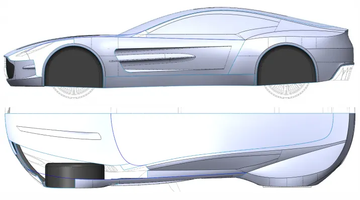
- The special features used in the door surface can seen in below PIC.11
PIC.11
g) Front wing Surface.
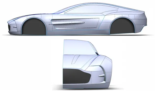
- Front wing is the nearer side surface to the bonnet and it covers the side of the bonnet and touches the front bumper and the side fender till door continues .
- Similar features we are used above surface but slight chances in each and every part of the modelling.
- After the all the follow ups the front wing looks like below PIC.12
PIC.12
- Now we almost created all the surface for the main body, next we will start separating the each and every surface but split tool and making as a one separate part file.
- And finally combined as a single assembly file as whole car of Aston Martin One-77.
h) Roof-1 Surface.
- In roof -1 we are splitting the roof top and split that into three part , front , middle, and rear surface.
- The front part of the surface represent as th front windshield .
- The middle part represent as the roof top in that we are creating some design to the roof top as follows in the study material .
- And the rear surface as the rear windshield of the car.
- Separate the front and rear windshield as a separate part.
- Create the new assembly file, and started importing the each part one by one.
- The main assemble as the ASTON MARTIN ONE 77-1 ASSEMBLY as mentioned earlier in the design methodology.
- it cover all the above surface we created till now as the whole assembly 1.
- Because we splitting into different part for the futures reference and the easy accessibility. of the surface, in the single file we created all the surface it may cause to error.
- We cant refer the some existing features or surface easily.
- In any error has occurred the whole file goes wrong.
- And Insert component in the assembly file started importing the Front and rear windshield on by one.
- Mating is the one of the important features in the assembly environment. How we are giving constraints to the sketches, like that matting in the three different DOF (Degree of freedom ) is important in the assembly environment.
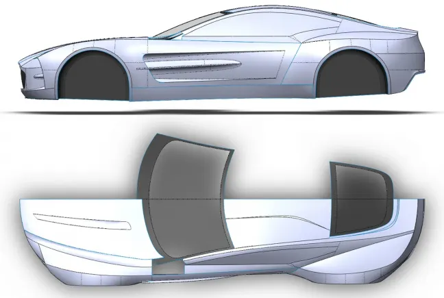
- After matting with three DOF we cant move the part by draigging it. or else we dragged the surface it will move from the position , now we can see the assembly -1 like below PIC.13
PIC.13
i) Door-1 Surface.
- Start separating the door sides from the main Part ASTON MARTIN ONE 77-1 FILE.
- Before that tiny surface are still pending around the door surface finish all those steps .
- And Split the door from the main body using SPLIT tool.
- We already created the profiles and special features of the door in the pervious modelling, but the outer surface only we created.
- Now we are going to see the mirror of car, door opening latches to give the better finish for the Door surface.
- The mirror is little complicated surface for creating when compared to few profiles, but same tools that we are going to use as previous.
- And door opening latches is the simple procedure if we follows the study material we can create it easily.
- Insert>Cut>With surface tool is used to cut the intersection surface, with reference of one surface cut the other surface that is intersect each other, we can see that mirror inside portion with the help of the outside bose/base thickness we cutted the inside thick surface and projected like mirror.
- Insert>Features>Keep Delete/Body tool is used to delete the offset surface and also the surface we want delete we create in the model.
- Insert>Cut>Extrude tool is used to cut the surface with the profile of sketch .
- Door surface is almost over we can start assemble the door surface to the main assembly 1 like the both the windshield.
- And above split the side windows as same above and follows the study material ,after the modelling over start assemble the side windows to the main assembly.
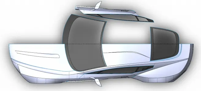
- we can see below the assemble file of all the above surface and the parts in PIC.14
PIC.14
J) Hood-1 Surface.
- By few sketches we separate the hood as the single part from the main body and adding additional features to the hood.
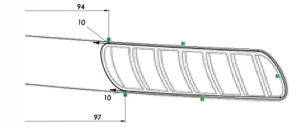
- At the sides of the hood we are going to split some portion started working on it as show below PIC15.
PIC.15
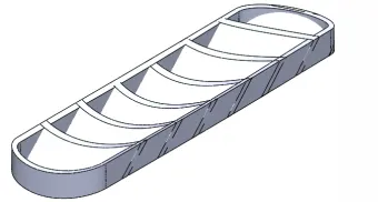
- If we follows the one by one step in the study material like split the sketched portion and offset the splited portion to below the hood surface at some distance mentioned .
- And started creating the new surface and move the surface using Insert>Features>Move/Copy near to the small portion.
- Make Linear Pattern tool pattern to 7 occurrences to front plane.
- Cut the surface to the previous sketch through all options, we removed the outer surface of the moved surface.
- And using cut with surface tool, cut the balance portion too, now it will look like below PIC.16
PIC.16
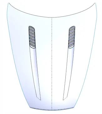
- Insert>Features>Combine Tools is used to combine all the tinny surface into one single surface and the whole bonnet looks like below PIC.17 .
PIC.17
- Similar procedure is used to the front wings portion as follows in the study material.
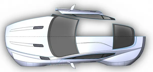
PIC.18
- The all assembly as inserted into the main assembly and looks like the above PIC.18
k) Rear bumper-1 Surface.
- In every surface creating in the earlier was only the simple surface but now taking the simple surface and separate as a single part and adding some additional features to each and every portion of the car in surface environment.
- Create the balance surface in the rear bumper like tail lamp portion, car spoiler, and the bottom surface of the bumper.
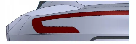
- In creating the tail lamp portion we use the following steps like as per profile split the surface from the bumper and offset the split surface ,by selecting the edge of the split surface create the ruled surface .
- And Knit the ruled surface with the original surface and the offset surface with the tail tamp .
- Fillet also used to make the sharp edges of the tail lamp into some radius and the tail lamp looks like below PIC.19
PIC.19
- Car spoiler is the easy procedure if we follows the study you can easily finish it soon.
- And going to the Rear bumper make the surface that need to the bumper and separate as a new part for adding extra features for the bumper.
- How we did for the hood small portion fins inserted , as procedure as follows but few steps that different from the hood.
- Start sketching in the front plane as per required sketch, and extrude the sketch till the surface we created near to the rear bumper.
- While extrude the boundary surface make click the thin features options to give thickness to the sketch .
- Using Insert >Features>Delete /Keep body delete the surface that help to extend the extruded surface in the bumper.
- Using Insert >Face>Delete tool is used to delete the sketch face from the extrude the surface ,it helps to create it like the shell inside the surface at on end.
- The face deleted option is mainly done for the trim the intersect portion of the bumper, using mutual trim select the extrude surface and the face at the bumper intersecting is also selected for trimming.
- Finally fins at the bumper is created in addition to that silencer portion is created at the rear bumper as follows
- Using Insert>Features>Shell tool is used to make the profile with thinkness for the closed surface sketches like circle, ellipse etc.
- And fillet the edges and slice the one side of the shell for the appearance of the silencer and trim the bumper at the silencer projected area.
- Move the Silencer using the Move/ copy from the features at required distance as per study material.
- Like the tail lamp the rear bumper lamp and the License plate is create at the bumper part it looks like the below PIC.20
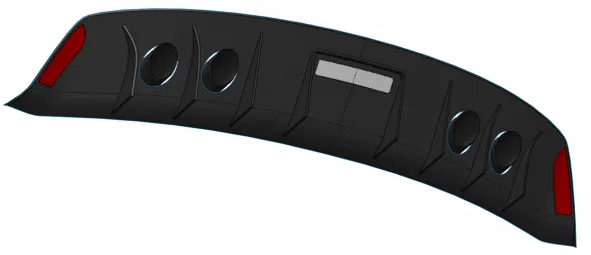
PIC.20
The assembled view will looks like the PIC.21
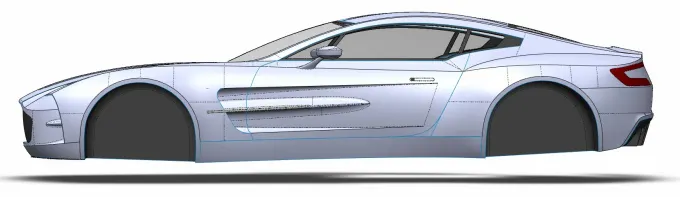
PIC.21
l) Grill Surface.
- Like previously done start separating the surface that need to give special features for the grill portion, and make it as the separate part file.
- Step by step follows the procedure give like offset the surface trim the intersected surface that is offset from the original surface.
- Knit the surface offset and trimmed intersection part.
- Start sketching the new vertical profile for the grill ,extrude the surface in-between the original surface, like wise create horizontal portion as similar to the vertical portion.
- Use cut with surface option cut the unwanted extra profile.
- Insert>Bose/Base>Fillet tool is used to fillet the thickened profile that is extruded and cut the extra edges while cut the intersect portion with surface.
- And finally add the license plate to the grill as per material follows and delete the body that helps to create the grill at 1st separate from the main part.
- Now we can see the Grill surface below PIC.22
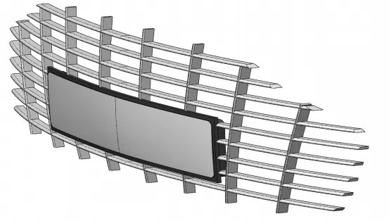
PIC.22
m) Light Surface.
The light is the one of the most important part in the car while travelling in the night without light we cant drive, its like the helps to focus the object at the outside environment to see the clear view for driving.
- Light is the another important part in the modelling more features for design and beauty is added to this modelling.
- Start separating the front light portion from the main part already created, use some sketch to split the light portion .
- And make that splitted portion as the separate part and started adding the extra features to it.
- Follows the procedure step by step you can add the features to the light.
- And for the light bulb inside the light surface create the separate surface and move that using the move/copy tool in the features.
- For that light bulb surface Insert>Bose Base>Revolve tool is used to create it.
- Offset the surface in the existing surface already created and use the surface to give additional features to the light bulb.
- Trim the unwanted parts, and make the profile to connect the light bulb and the offset surface as follows in the study material.
- Insert>Features>Intersect option is similar to the cut with surface tool, but some slight changes to that, apart from the intersect portion it will trim all the surface outside it and click the merge option in that so that it combined as a single surface.
- And along with mini bulbs also making features to the light part.
- Use sketch create the circle and extrude it for that mini bulbs.
- Also like typical procedure we used for the hood and front wings the fins that added at the side of the front light part as follows in the study material and you see the front light as below PIC.23
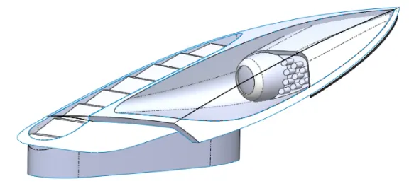
PIC.23
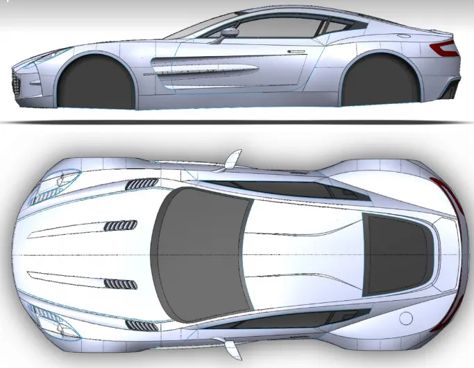
- Now we almost done the one half side of the car, Knit the surface as a single surface in the main part body hide the separated parts in the main assemble so that it wont reflect in the Main assembly .
- And mirror the knit surface you can see the model in the main assembly like below PIC.24
PIC.24
n) Wheel Surface.
Wheel is the important part in the automobile industries because wheel is used to move the body from one place to another it is also called as locomotive. For the generation era moving from one place to another place a major role , wheel doing that in the automobile to move from one place to another .The general name in automobiles called as wheel .
- Coming to our model wheel consist of tier and the rim we are going to see in the below steps as follows.
- We are doing two types of rim and the two types of tier, it don't have a major difference in creating the model.
- We can easily change after creating one model to other by changing simple dimension in the sketches.
- One is RIM 27 indicated the width of the rim is 27 cm, another is RIM 34 similarly.
- Likewise same concept for the TIER 27 & TIER 32 as follows.
- Start the new part and change the units to CGS, save the file name as RIM 27.
- Sketch on the new plane and revolve the sketch we got the rim basic modelling.
- Now step by step adding the additional features to the rim for the elegant look and beauty.
- And start new sketch, revolve to the some degree and untick the merge result or else it will merge with the existing rim surface we created.
- For the new shape to the above revolved surface use extrude cut tool and cut the revolved surface through all option in the extrude cut.
- Fillet the extruded cut surface with variable fillet, use the fillet surface edge , create the loft surface above the fillet surface.
- Cut the above surface of the lofted features with cut with surface tool.
- And one more features added to it use the new sketch revlove, bose base and move to the rim features centre and combine to one surface.
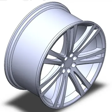
- Rotate the combined part using the circular pattern and RIM 27 looks like below PIC.25
PIC.25
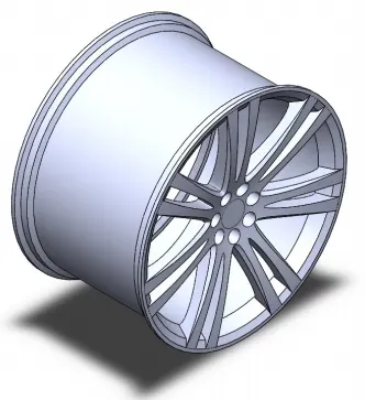
- Same procedure and copy the RIM 27 and save as the RIM 34 Change the width of the 1st profile we created instead of 27 give 34 and exit the sketch.
- All other changes will be done according to the previously made and RIM 34 looks like below PIC.26
PIC.26
- Start creating the new file for TIER 27 and sketch the profile according to the study material, here revolve command is use frequently for making the wheel surface.
- Create a new sketch for making the additional features to tier, and use Insert>Revolve>Cut tool is used to cut the revolved previous sketch.
- In tier mostly we use the extrude cut option for making the required profile, and use the extrude cut make the circular pattern for duplicating the extrude cut surface on the tier.
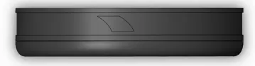
- Uncheck the geometry option while doing the extrude cut , then pop up window will appear select the tiny portion in-between two pattern select that body and click ok. you can see like the below PIC.27
PIC.27
- And by the different way the we can cut the above tier surface using Insert>Cut>Sweep create the profile perpendicular to the tier and use one guide profile to sweep the profile ,the guide profile should be cut the top of the tier surface and validate it.
- And use circular pattern select the extrude cut features and revolve around the tier surface as follows in the study material, typically do the circular pattern for before extruded cut around the tier surface .
- Mirror the whole features we did and we can see the full portion of the TIER 27,similar procedure to follow as done for the RIM 27 transformation to RIM 34.
- And we can see the TIER 27 and TIER 34 as below PIC.28
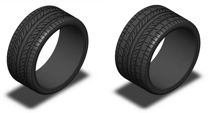
PIC.28
p) Brake disk .
A disc brake is a type of brake that uses the callipers to squeeze pairs of pads against a disc or a "rotor” to create friction. This action slows the rotation of a shaft, such as a vehicle axle, either to reduce its rotational speed or to hold it stationary. The energy of motion is converted into waste heat which must be dispersed. Brake disk is the one of the part in the car and final part in our the 3D modelling.
- Open the new part model for the creating the brake disk it also includes the calliper. Start with sketch for create the disk surface .
- Revolve the sketch we will get the disk surface and follow the features used in the material.
- Insert>Pattern Mirror>Curve drive pattern tool is the new tool we used so far, it helps to pattern the profile along the guide curve we formed.
- And use the circular pattern for the pattern we already did so that we can pattern through all the part of the disk.
- Using the sketch Extrude the surface in-between gap of the two revolved surface and validate ok.
- The disk portion is over as shown in the below PIC.29
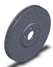
PIC.29
- Next to the disk the calliper part is going to model, start the new part file and started sketching the profile.
- The calliper is the part for the part we have create More sketches and extrude surface plays the major role in it.
- And extrude cut also used many times for creating this surface, you can see in the study material and follows step by step.
- The typical command we used earlier like, sweep, extrude cut, fillet, loft and combine.
- After finish all the procedure we can get the one side of the model, and we have to mirror the features we will get the calliper part and assemble the both the disk and calliper as on assembly as shown below PIC.30
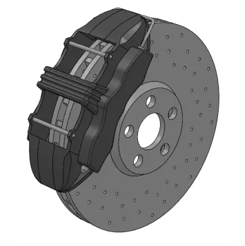
PIC.30
q) Emblem .
Emblem is one of the important part to identify the model of the car or automobile. Once we think about the automobiles its comes to the brand name, the brand will represent through the emblem of the car. Now we are going to design the ASTON MARTIN emblem in this model.
- Start sketching in the new part file, in the sketches we creating mostly as in the random figures only.
- By considering the design and look it will represent the emblem.
- In the emblem surface most of the tool we using is extrude the surface as per the profile and extrude cut the unwanted surface .
- For extrude surface we will create the thin features for the profile of the emblem.
- And follows the procedure step by step we can able to create the emblem full surface.
- Mirror the above all features we will get the emblem model we want to create
- Select the top surface start sketch on the surface in the sketch create the text using the text tool , type the name as ASTON MARTIN, below we have font style, bold, italic , colour as per our need and design.
- The last tool in the ASTON MARTIN modelling Insert>Features>Flex tool it used to flex in means of bend, twist, tapering, stretch along with degree and the radius we want for the emblem.
- And insert the emblem into the main assembly in the front and rear side of the model .
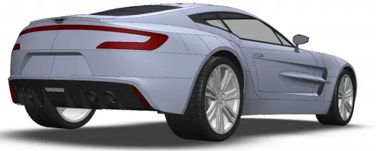
- We have now finished the ASTON MARTIN ONE -77 outer surface fully as show in the below PIC.31 & PIC.32
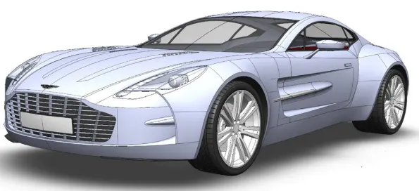
PIC.31
PIC.32
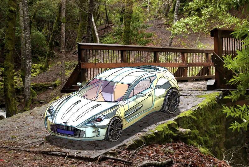
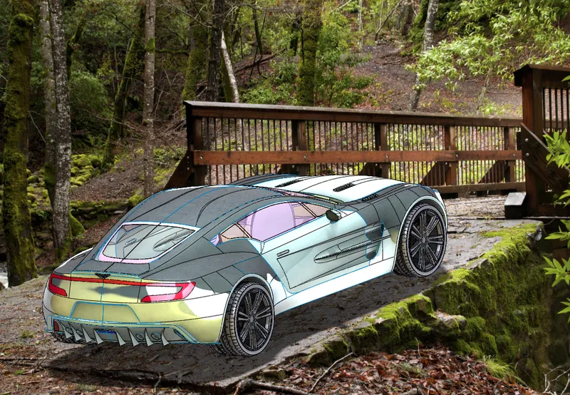
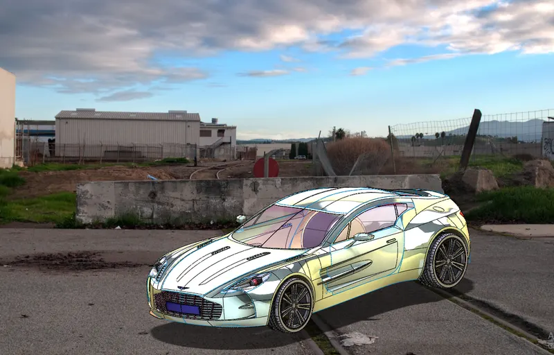
RENDERING OF THE ASTON MARTIN ONE 77
The rendering is the additional beauty appearance of the model we have created with background effect and the material properties of the surface we created as shown in below PIC.
PIC.33
PIC.34
PIC.35
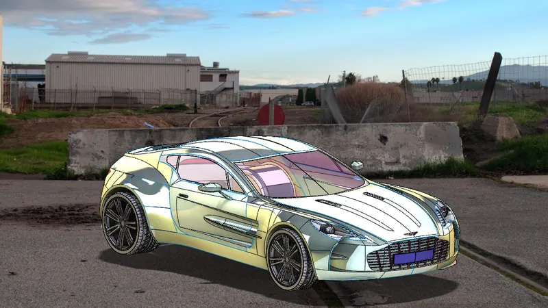
PIC.36
CONCLUSION.
- We came to conclusion of the ASTON MARTIN ONE 77, from the starting of the surface till end we have created more number of surface for the model, and each and every surface have unique features and tools helped for creating the model. In this model we have covered almost all the tools that present in the Solidworks software and get the better idea of user interface throughout the model creation and learned the hand on experience in the practical and reality of the industrial standards in the outside job environment.
- Really it is the good course for the students who have keen interest in the automobile 3D modelling world.