Week 8 - Challenge 1 - Draft Analysis on a Fan Cover
DRAFT ANALYSIS ON A FAN COVER
TREE STRUCTURE
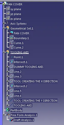
- Publications: In my catia thier is no publishing options to publish the below content, for your reference i am enclosing the screenshot of the catia window.
- Tooling Axis
- Class A surface
REPORT
INTRODUCTION
Using the class A surface of FAN COVER we are going to check the draft analysis and the tooling axis creation.
PROCEDURE
* Import the class A Surface into the CATIA workbench
* And check the class A surface is fully closed without any gap in the surface , using the JOIN and BOUNDARY option in the surface and wireframe design
* After checking the surface of the class A is closed, check the possibility of the tooling axis in 3 axis x ,y , z.
*Tooling axis is the most important in the draft analysis.
* In the FAN COVER class A surface we checked the 3 axis, at the top of the fan cover their is hole so in X & Y if we select as the tooling option we need separate operation for creating hole in the fan cover .
* So in the Z direction it will be convenient for doing draft analysis.
*And in the Z axis too we have to check some of the consideration before creating the tooling axis.
* So we created at the top of the fan cover ,create a new axis system in that axis system origin at the top of the fan cove we created a dummy tooling axis for our reference .
* And after that we intersect the fan cover using the new axis system in the XZ and YZ plane, so that we can check the any problem that may occur in the draft angle .
* 1st using the XZ plane intersect portion create the two lines which is parallel to the dummy tooling axis , using that two lines create the bisecting line in the Z axis .
*Because we checked earlier in the Z axis only we can easily perform the draft analysis, so selecting the z direction create the X Tooling axis .
* Similarly using YZ intersection of the fan cover create the Y Tooling axis .
*Now we have two axis tooling using that both create the bisecting line that is the original tooling axis.
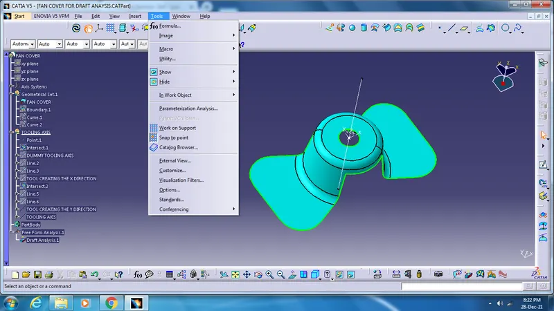
* After that publish the tooling axis and the class A surface for the easy access using tools option.
* Now go to INSERT - ANALYSIS - FEATURES DRAFT ANALYISIS .
*In that draft analysis various option are their to set the quick draft analysis mode or full draft analysis mode to set the draft angle is allowable to the analysis which is undergone .
*In the direction option click the compass and drag near to the fan cover and fix in the tooling axis and lock the compass
*And using analysis under the running point click that and select the any portion of the fan cover you will get display the draft angle is passing for the draft angle we set.
*If not it will project in the different colour we set in the mode .
*We also check the mode by changing the draft angle, but maximum draft angle is 3 deg.
Screenshots of the Draft analysis report.
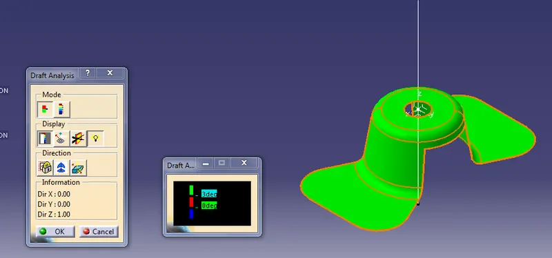
FIG.1- ISOMETRIC VIEW
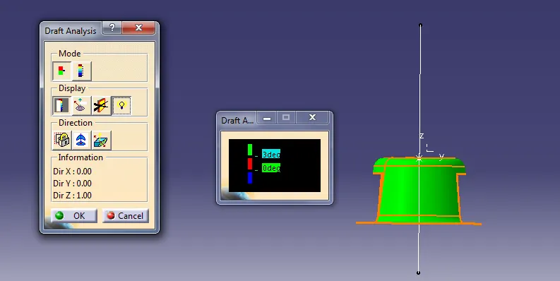
FIG.2 FRONT VIEW
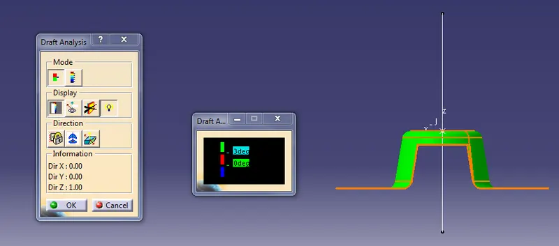
FIG.3 SIDE VIEW
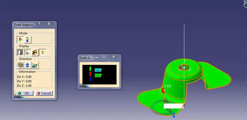
FIG.4