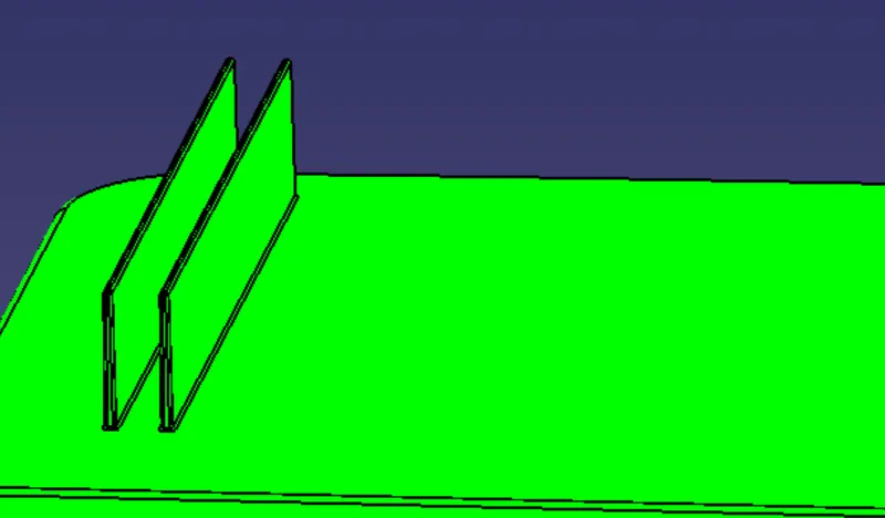
Week 9 - Attachment Feature Creation - Challenge 1
WEEK-9 CHALLENGE-1
RIB CREATION
AIM
This challenge aims to create the rib structure for the design of the coin holder component following the design rules.
THEORY
RIBS
Ribs are generally added to the primary wall of a plastic part for structural purposes. This could help the part resist deflection under load or resist warpage. The plastics designer must always consider manufacturability issues when adding ribs to the primary wall. These include part ejection, air venting during mold filling, cooling, and mold filling and packing effects. Ribs increase the component's strength locally without adding much weight to the element. Ribs are usually cleared in the central tooling axis, and in some cases, the side core tooling axis can also be used.
DESIGN RULES
There are many design rules to be followed while designing ribs of a plastic component. These rules come because of the varying thickness of the rib structure. These rules are derived from many trial experiments and are followed by most of the OEMs:
1. Draft
A minimum of 0.5 degrees of the draft has to be provided to the outer surfaces of the rib with respect to the tooling axis. This draft is to ensure the safe and easy ejection of the component.
2. Thickness
The thickness of the rib at the bottom (w) has to be at least 40 percent of the main wall thickness of the component (t).
w= (0.4 x t)
3. Height
The Rib height/ depth cannot be more than five times the thickness of the wall.
H ≤ (5 x t)
4. Thickness at the top face
The minimum thickness at the top face (T) has to be at least 0.75mm for any rib.
T ≥ 0.75mm
5. Optimal fillet radius
The optimal fillet radius value for the rib design is 0.25mm, the maximum value.
R ≤ 0.25mm
6. Rib root thickness
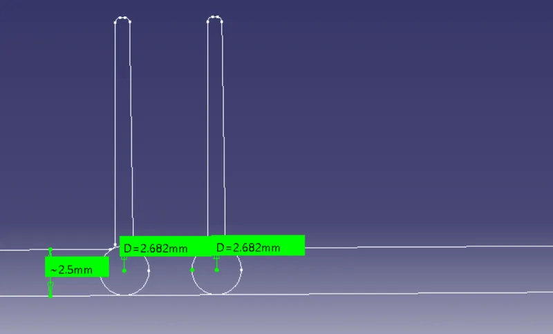
Rib root thickness can be defined as the diameter of the circle tangent to the bottom surfaces of the rib and the bottom surface of the inside/ outside wall of the component. The difference between the maximum rib root and wall thickness has to be around 30 percent.
D ≤ (1.3 x t) mm
7. Spacing between the ribs
When two or more ribs are needed to strengthen the component, then the spacing between those ribs becomes another design factor. The height ratio to the spacing between ribs should always be less than 3.
H/X < 3
PROCEDURE
Given the wall thickness of the component, t = 2.5mm
1. Creating the rib
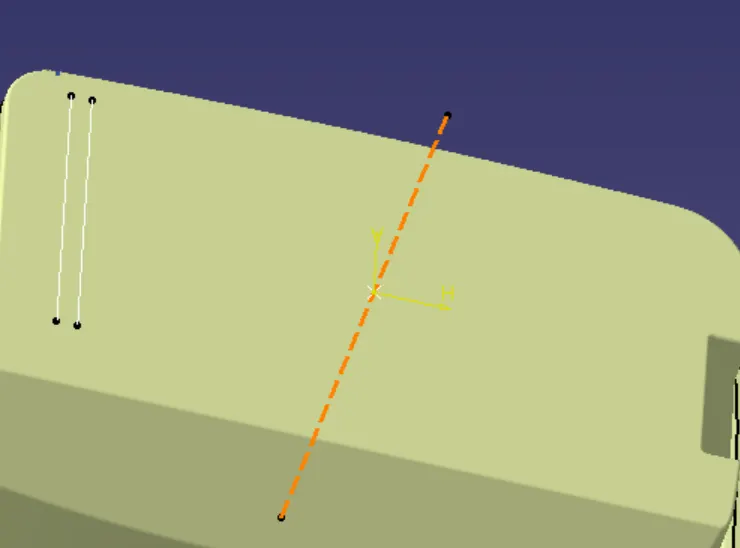
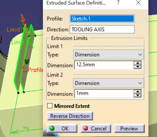
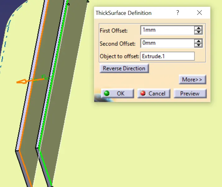
First, we need to create the shape of the rib using the sketch option and then extrude the sketch by 12.5mm (we get this value by multiplying the thickness (t) by five times) with respect to the tooling axis. Now, the surface can be thickened by using the thickness feature in the part workbench, and the thickness value is observed to be 1mm (40 percent of the thickness (t)).
2. Drafting and filleting
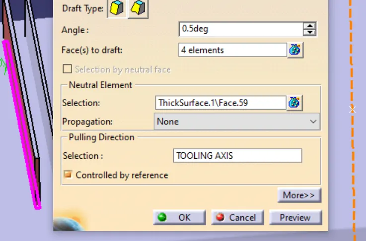
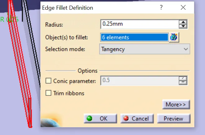
The faces that we obtain are not drafted. These faces are now drafted by 0.5 degrees with respect to the tooling axis using the draft option. These drafted faces are directly joined to the main body, and a nominal value of 0.25mm fillets every sharp edge.
3. Analyzing
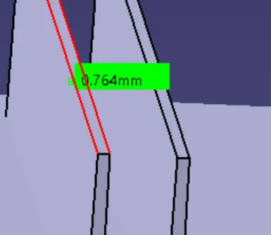
Now the maximum thickness of the feature at the top before filleting is measured, and if the observed value is below 0.75mm, the design is modified. Furthermore, another observation that needs to be taken is the rib root thickness; this can be obtained using the intersection and the circle features. The value for the rib root thickness has to be less than 3.25mm.
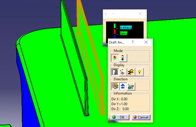
4. Draft analysis
Finally, draft analysis is performed on the component in the tooling direction to check if any surfaces do not clear the minimum draft condition.
FINAL MODEL