Week 9 - Attachment Feature Creation - Challenge 1
RIB DESIGN
Objective :
To create the rib for the Centre console coin holder, considering the design rules.
Procedure :
TOOLING AXIS
The tooling axis is the direction on which the mould is open. Proper tooling axis is required to satisfy the draft on the faces of the plastic part to be produced.
Hence, it is observed that no draft is given to the CLASS A surface, we are not able to modify it. So, there is no possible way to create the tooling axis along X and Y directions. If we create, both lines lie in the same point and same direction. Therefore, the obtained dummy tooling axis is the tooling axis for the given CLASS A surface.
The tooling axis is created by extracting the base surface of the coin holder and creating a point at its centre. From its centre, a line is created in vertical direction.
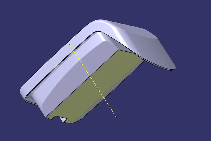
DRAFT ANALYSIS
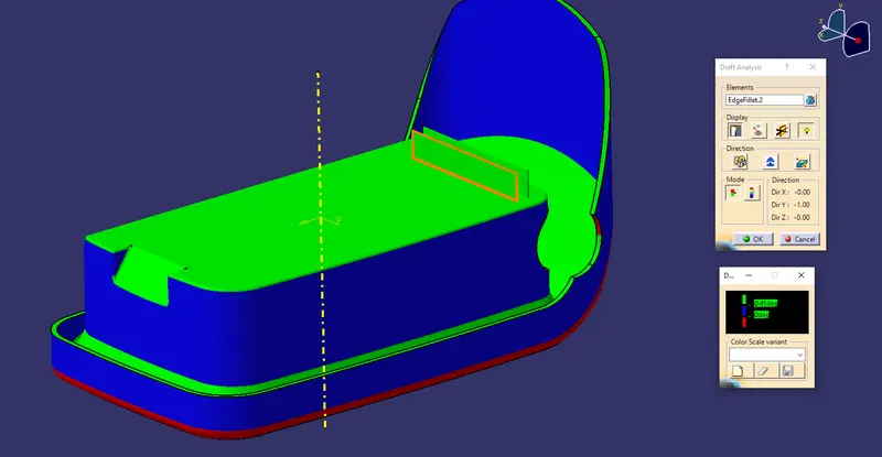
Here, it is observed that, the vertical walls are having no draft angle which are indicated by the blue colour. This means, CLASS A surface designer, does not provide the draft to the surface. We are not able to modify this without higher authorities in industry point of view.
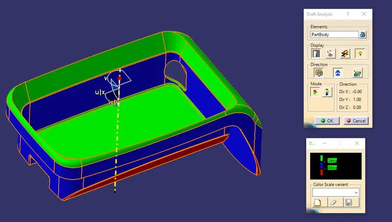
RIB DESIGN
RIB - Ribs are thin wall protrusions that extend perpendicularly from a wall or plane. If a wall is too thick on a part, it can cause warping and shrinkage in parts, often causing the whole design to be rejected. Ribs solve this problem by providing additional support for thinner walls. It can effectively improve the rigidity and strength of plastic parts.
Design rules for Rib -
- Draft - a minimum of 0.5 degrees draft is required on each side of the rib.
- Rib thickness - The maximum thickness allowed is 40 % of part thickness.
- Height of Rib - maximum of 5 times of the part thickness
- Spacing between Ribs - The height to spacing width ratio of rib should 3:1 for steel / 2:1 is mostly preferred.
- Thickness at tip - A minimum thickness of 0.75 mm is required at the tip of the rib.
- Fillet radius - maximum of 0.25 mm.
- Rib root thickness - It should be less than 130% of thickness of part
Create the line on the bottom side of the given coin holder as shown
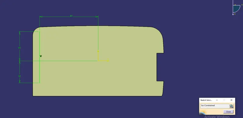
Extract the line created using the extrude surface feature by following the design rules. The maximum height of the rib should be 5 times of the part thickness.
`2.5 xx 5 = 12.5 mm`
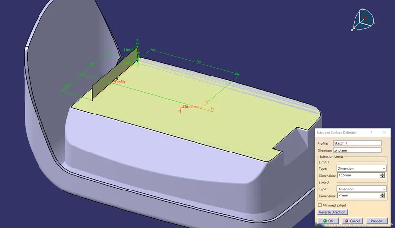
Add the material to the surface extruded. The thickness of the rib should be a maximum of 40% of the part thickness.
`2.5 xx frac{40}{100} = 1 mm`
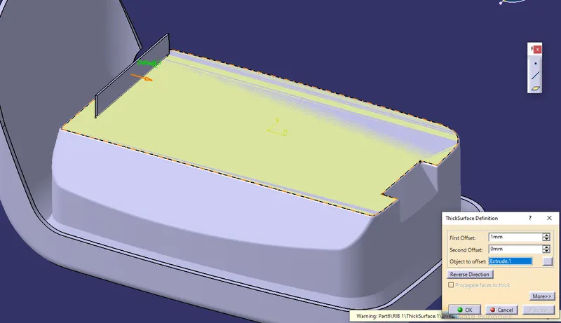
Apply draft to the faces of the rib created. The minimum draft angle would be 0.5 degrees.
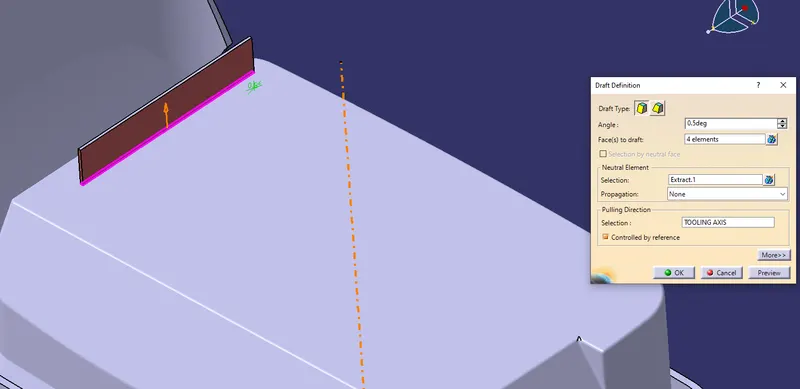
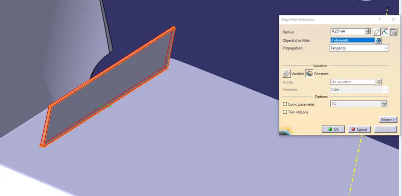
Add the rib to the main body and apply fillet.
The fillet value should be maximum of 0.25 mm
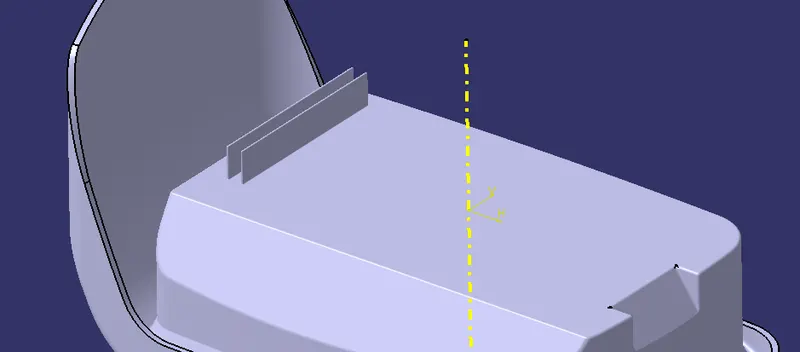
Now to create the another rib
Go to sketch and create the another line and extrude it. Do the same steps as before. Draft it and add with the body. Finnally, apply fillet
Now check for rib root thickness
Create the intersection curve as shown in below picture by creating the new plane
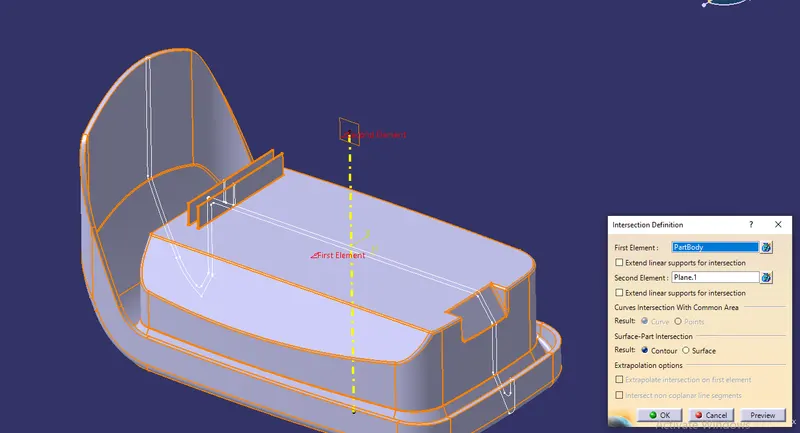
Views
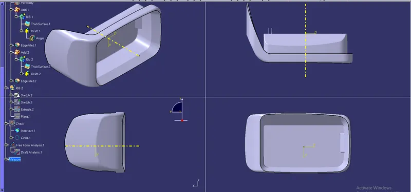
CHECKING FOR DESIGN STANDARDS
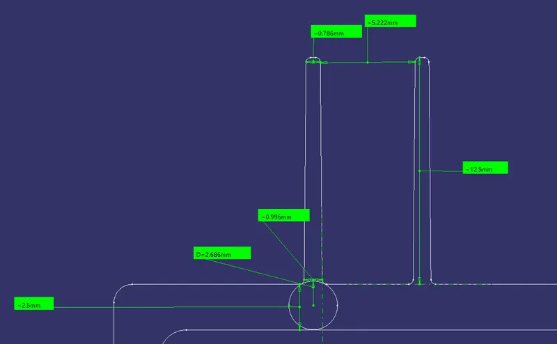
From the above picture, the thickness of the part is 2.5 mm
- Minimum draft of 0.5 degrees is given.
- Rib thickness should be maximum of `0.4 xx t` which equals to 1 mm, here the max width is less than 1 mm which is 0.996 mm
- Height of rib should be maximum of `5 xxt` which is equal to 12.5 mm, here the height obtained from the measurements is also 12.5 mm
- Spacing has the ratio of height of rib to distance between the two adjacent ribs should be less than 3 mm, here `frac{12.5}{3} = 4.166` which is also safe.
- Thickness at tip must have a minimum value of 0.75 mm, here we have 0.78 mm, which is acceptable.
- Fillet is given as 0.25 mm which satisfy design rules.
- Rib root thickness should be less than 30% of part thickness, which is `1.3 xx 2.5 = 3.25`, here we have 2.68 mm.
From the above points, all the design rules are satisfied, hence modelled ribs are valid.
DRAFT ANALYSIS
The below picture shows the final draft analysis on the part. Here the ribs does not have negative angle which are coloured by blue. The green surfaces indicate that they having the minimum draft of 3 degrees. But ribs are provided with the draft of 0.5 degrees. So they are in blue colour.
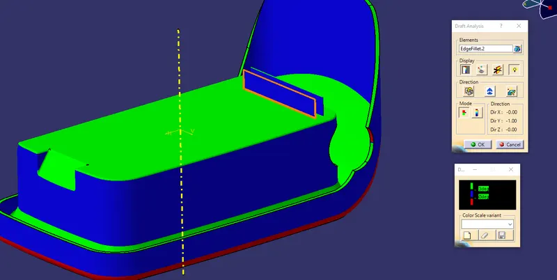
If we reduce the minimum draft angle to 0.45 degrees
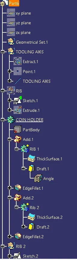
Tree structure :
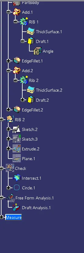
Conclusion :
For the given coin holder, tooling axis created by considering the draft angle requirements. The feature attachment of the rib is also done by design standards.
Thank You