Week 9 - Attachment Feature Creation - Challenge 1
Creation of Rib for the Centre Console Coin Holder
Aim: - The aim of this report is to create the Rib for the center console coin holder considering the design rules. Also, to perform draft analysis on the final component(with ribs) in catiaV5(Computer-aided three-dimensional interactive application).
Objective: -
- To create the Rib for the center console coin holder considering the design rules.
- To define the proper function of ribs in design parts.
- To explain the design rules considered while creating a rib in detail.
- To create the tooling axis for the coin holder model meeting the requirements of the draft angle.
- To perform draft analysis on the final component(with ribs).
- To explain the bisecting method used in order to create the tooling axis for the coin holder model.
Theory: -
- Rib: - Rib provide a means to economical stiffness and strength in molded parts without increasing overall wall thickness.
They also facilitate: -
- Locating and arresting components of an assembly
- Providing alignment in mating parts
- Acting as stops or guides for the mechanism
The examples of the Rib are shown in Figures 01, 02 & 03.
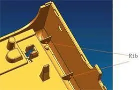
figure 01: - Example of Rib
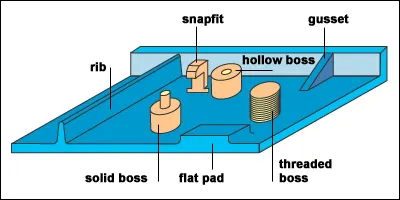
figure 02: - Example of Rib
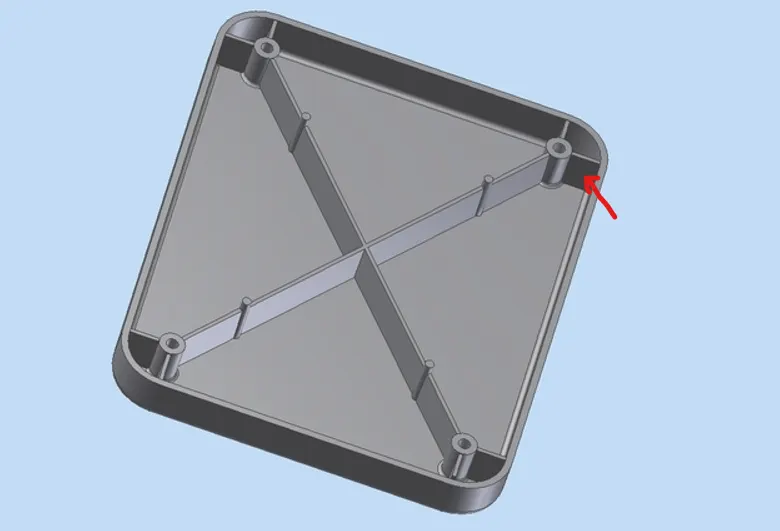
figure 03: - Example of Rib
2. General guidelines for Ribs and part design: -
This section deals with general guidelines for Ribs and part design.
- Proper Rib design involves five main issues: -
- Thickness
- Height
- Location
- Quantity
- Manufacturability
- Consider the below issues carefully when designing Ribs: -
Thick ribs often cause sink marks and in turn cosmetic problems on the opposite surface of the wall to which they are attached. The material, rib thickness, surface texture, color, proximity to a gate, and a variety of processing conditions determine the severity of the sink.
Sink marks are the areas in a molded part where the surface is deformed into a depression. The depressions typically occur in areas of thick geometry and are caused by uneven cooling of the injection material. This shrinking begins pulling the outer surface in, potentially collapsing the wall or deforming the part. The example of the sink mark is shown in figure 04.
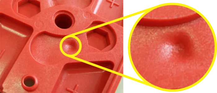
figure 04: - Example of the Sink mark in plastic part
Highly glossy, critical surfaces may require thinner ribs. Thin-walled parts(<1.5 mm) can often tolerate ribs that are ticker than the percentage in the guidelines. On parts with a wall thickness of 1 mm or less, the rib thickness should be equal to the wall thickness. Rib thickness also directly affects moldability. Very thin ribs can be difficult to fill. Because of flow hesitation, thin ribs near the gate can sometimes be more difficult to fill than those further away. Flow entering the thin ribs hesitates and freezes while the thicker wall section fills. Ribs usually project from the main wall in the mold opening direction and are formed in blind holes in the mold steel. To facilitate part ejection from the mold, ribs generally require at least one-half degree of draft per side. More than 1 degree of draft per side can lead to excessive rib thickness reduction and filling problems in tall ribs.
Generally, Taller ribs provide greater support. To avoid mold filling, venting, and ejection problems, standard rules of thumb limit rib height to approximately 5x the rib-base thickness. Because of the required draft for ejection, the top of tall ribs may become too thin to fill easily. Additionally, very tall ribs are prone to buckling under load. If you encounter one of these conditions, consider designing two or more shorter, thinner ribs to provide the same support with improved moldability as shown in figure 05. Maintain enough space between ribs for adequate mold cooling: for short ribs allows at least two times the wall thickness.
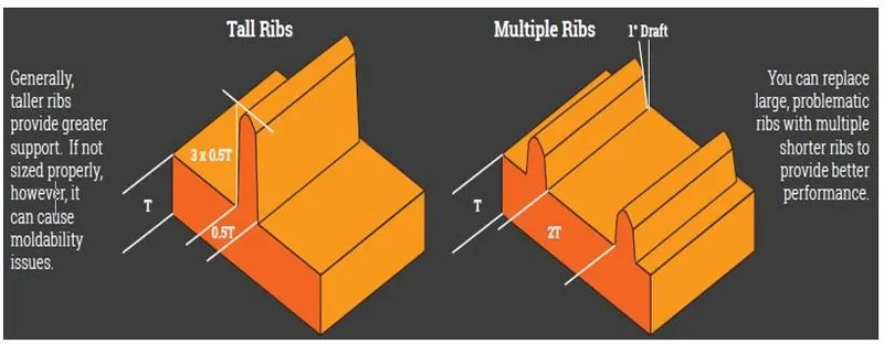
figure 05: - Example of multiple Ribs
3. Design rules: -
- Part design rules for rib creation: -
- The nominal wall thickness of a plastic component is 3mm.
- A deviation of ±30% from the wall thickness is accepted.
example: - for 3 mm thickness. 2.1 mm minimum and 3.9 mm maximum accepted.
iii. The ideal draft for a component is 3 degrees.
- Rib design rules: -
- Rib thickness (w): -
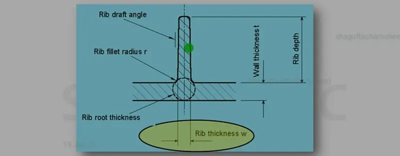
figure 06: - Rib thickness (w) rule
Rib thickness should be 0.4*t (t = nominal wall thickness). Measure the base thickness of rib at the tangent of radius, if radii are modeled in. The larger the area at the base of the rib, the more retained heat. The retained heat causes more shrinkage, which causes sink defects.
ii. Rib depth: -
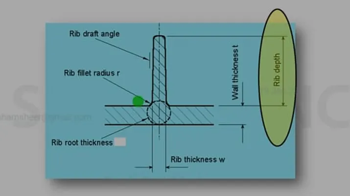
figure 07: - Rib depth rule
Rib depth or height should be ≤ 5*t (t = nominal wall thickness). It is limited by draft and thickness requirements.
iii. Rib draft: -
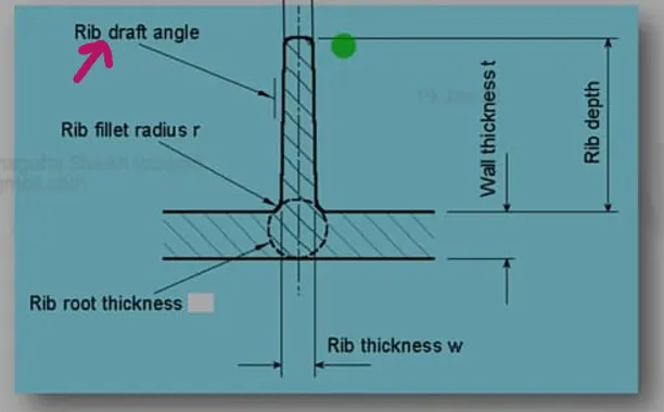
figure 08: - Rib draft rule
The draft on ribs should be ≥ 0.5 degrees.
iv. Rib fillet radius (r): -
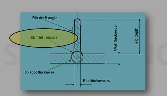
figure 09: - Rib fillet radius rule (r)
The optional rib fillet radius is 0.25 mm maximum. Do not want to significantly increase rib thickness. Must not violet 40% of the wall thickness requirement.
v. Rib tip thickness: -
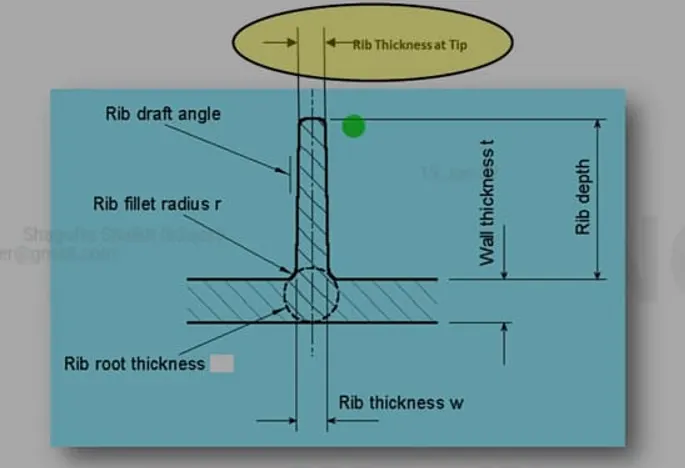
figure 10: - Rib tip thickness
The thickness of the rib tip should be ≥ 0.75 mm.
vi. Rib root thickness: -
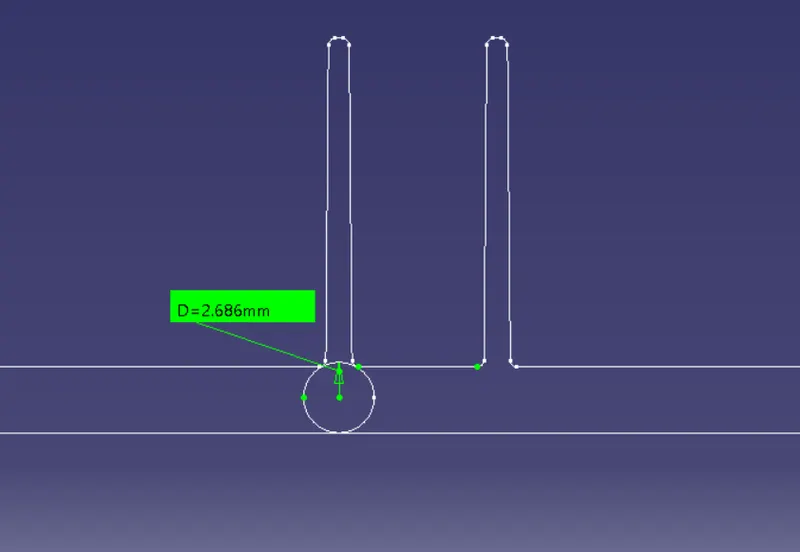
figure 11: - Rib root thickness
The rib root thickness will be ±30% from the wall thickness. The diameter of the circle shown in figure 11 is nothing but the rib root thickness. For example: - if the wall thickness of the component is 2.5 mm then the rib root thickness will be ranging between 1.75 - 3.25 mm.
vii. Spacing between two ribs
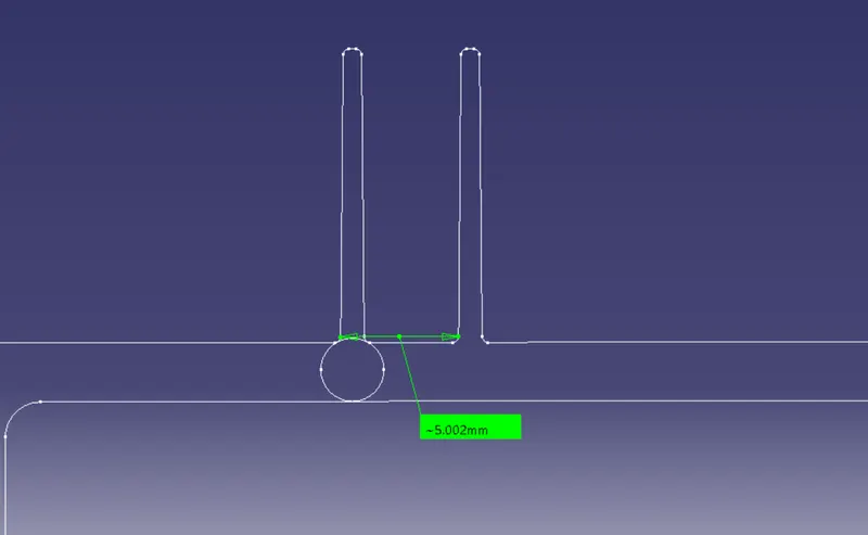
figure 12: - Spacing between two ribs
Ribs should be spaced so that the steel between the ribs is at a height /width ratio which is 3:1 for steel and 2:1 is preferred. Prevents thin steel conditions which lead to cracking.
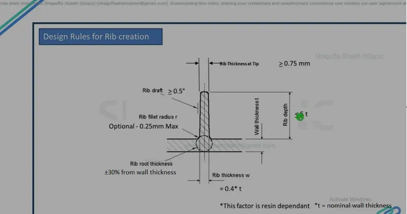
figure 13: - Recap of Design rules
4. Tooling axis creation for coin holder model(with ribs): -
The tooling axis indicates the direction along which the tooling or the manufacturing of the component will be done. In catia, the tooling axis is used to create C surfaces using the sweep option. There are many methods for the creation of the tooling axis and bisecting method is one of them.
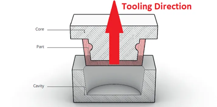
figure 14: - Example of tooling axis direction
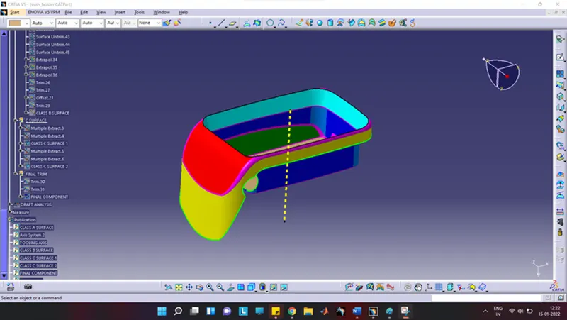

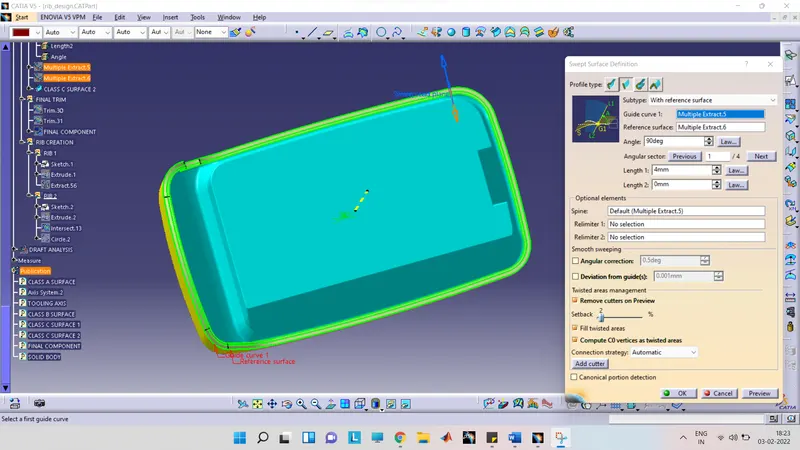
figure 15: - Use of tooling axis in catia (C surface)
The steps involved in creating tooling axis using the bisecting method are as follow: -
- Check continuity or quality of Class A surface
- Selection of best possible tooling direction
- Creating dummy tooling axis
- Tooling clearance for respective directions
- Creating final tooling axis
step1: - Check continuity or quality of Class A surface
Product designers should check the continuity or quality of the class A surface given by the class A engineer. They should ensure that there are no gaps between the surfaces using the boundary or the join command in catia.
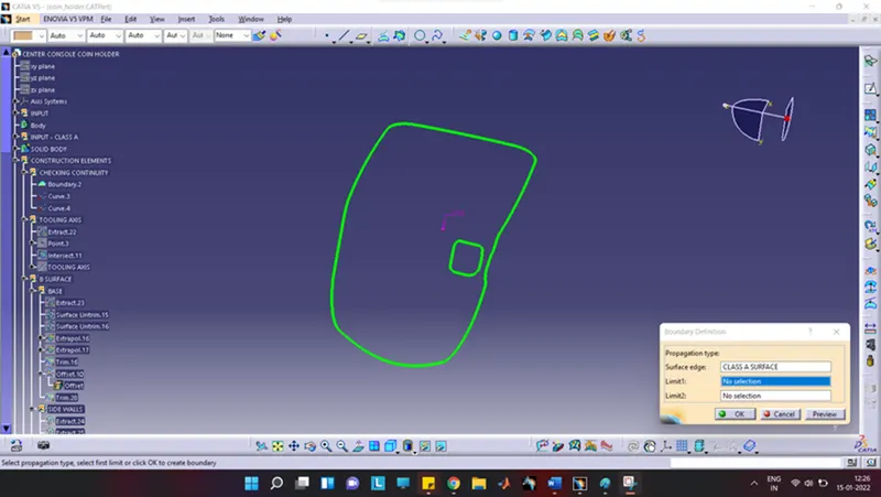
figure 16: - Checking the continuity (using boundary command)
step2: - Selection of best possible tooling direction
The tooling direction should be in such a way that it should cover the complete component along with its holes, undercuts, etc. in the main tooling. The product designer should also avoid side cores because the side cores generally increase the manufacturing cost of the component.
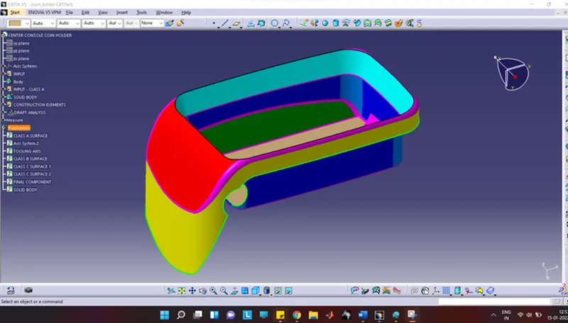
figure 17: - Coin Holder Model
After checking all the directions of the model shown in figure 17, it is found that most of the faces in the model are without a draft like shown in figure 18. Hence, the manufacturing of such components is impossible. A product designer should immediately concern the Class A engineer for such cases.
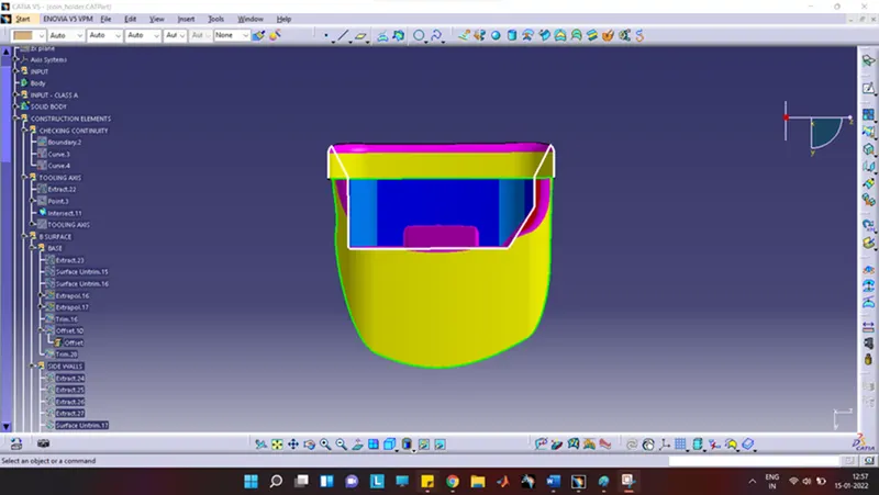
figure 18: - x-direction
Just for time being in order to continue the design further for creating the final component out of the surface model, one can select the y-direction as a tooling direction as shown in figure 19.
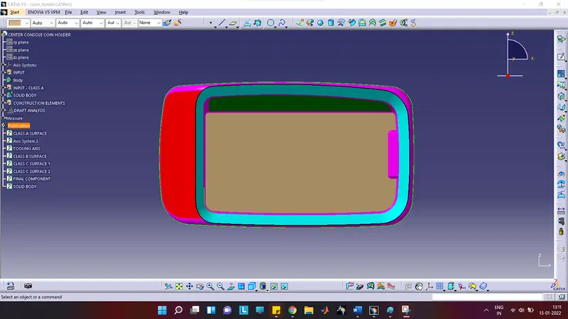
figure 19: - y-direction
step3: - Creating dummy tooling axis
The dummy tooling axis is a line or an axis created at the center along the y-direction as shown in figure 20. The dummy tooling axis is used just as a reference and it is not the real tooling axis.
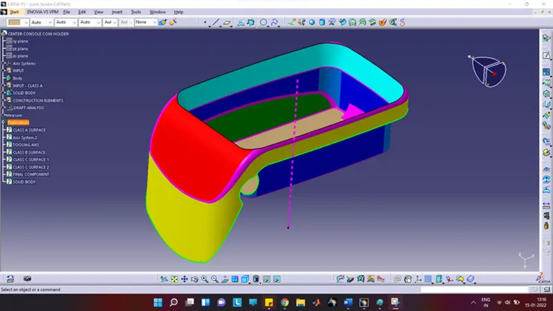
figure 20: - Dummy tooling axis
step4: - Tooling clearance for respective directions
This step is skipped because we directly chose y-direction as our tooling direction as shown in figure 19 and made the tooling axis directly for the y-direction taking the center of the component as shown in figure 21. Basically, there is no involvement of bisecting method in this case.
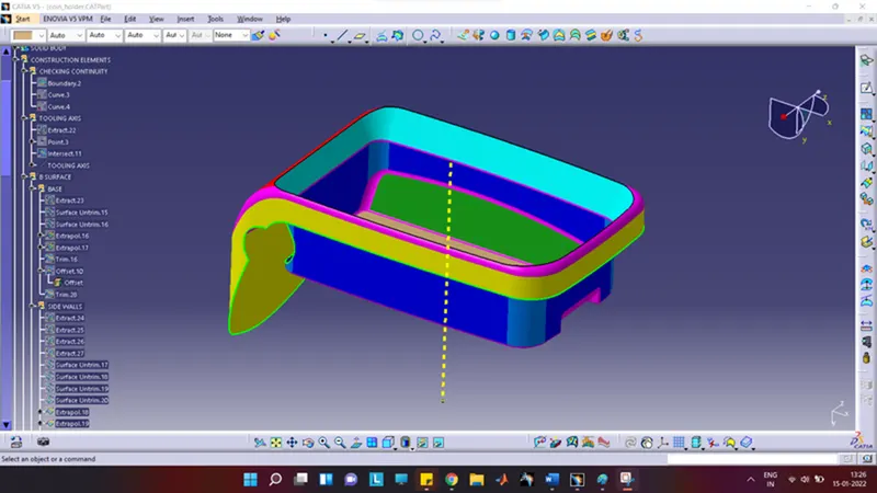
figure 21: - Main tooling axis
5. Publication: -
Using the publication option, the important parts of a model are easy to search.
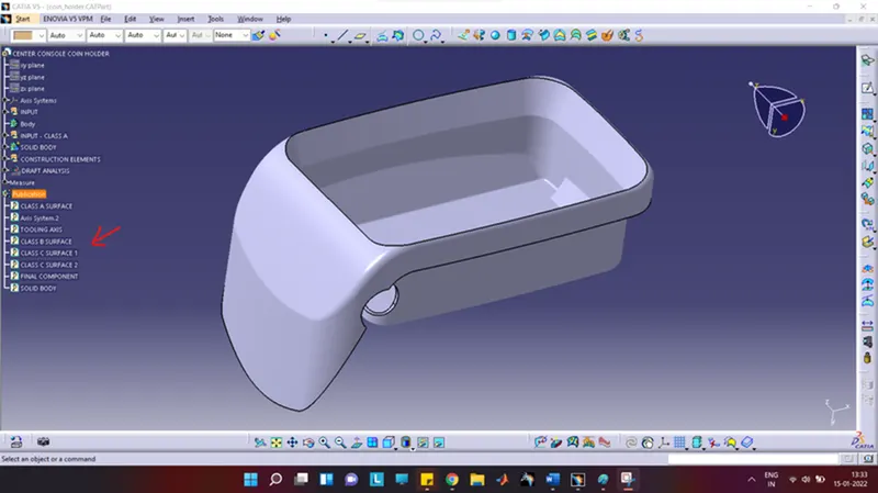
figure 22: - Coin Holder Model, Class A, B, and C and tooling axis are easy to search
6. Draft Analysis on Coin Holder Model (with ribs): -
Draft: - Draft is providing angles or tapers on product features such as walls, ribs, posts, and bosses that lie parallel to the direction of release from the mold that eases the part ejection.
The draft is required on all parts in the direction of mold movement in order to allow parts to release or eject from the mold properly. The draft is the angle at which the part is tapered to allow it to release. As the part cools, it tends to shrink to the core side of the mold. Adding draft helps the part to release. 3 degrees is the nominal draft. Whereas, 0.5 degrees can also be manufactured at ribs. 7 degrees for the textured faces.
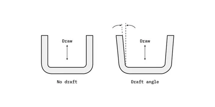
figure 23: - Example of draft
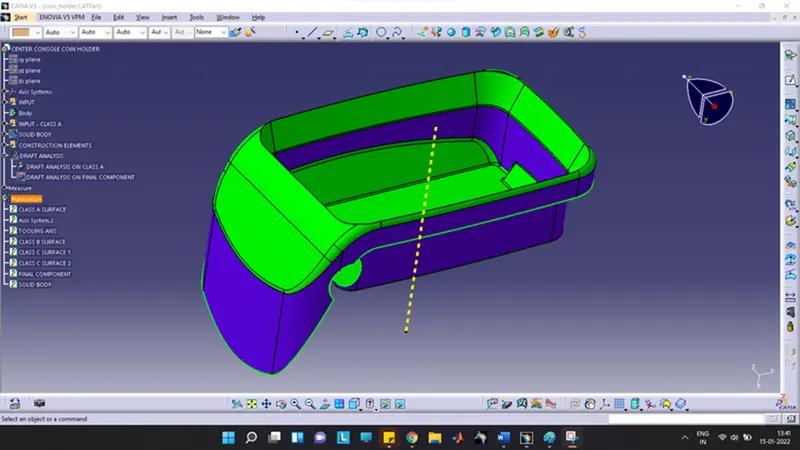
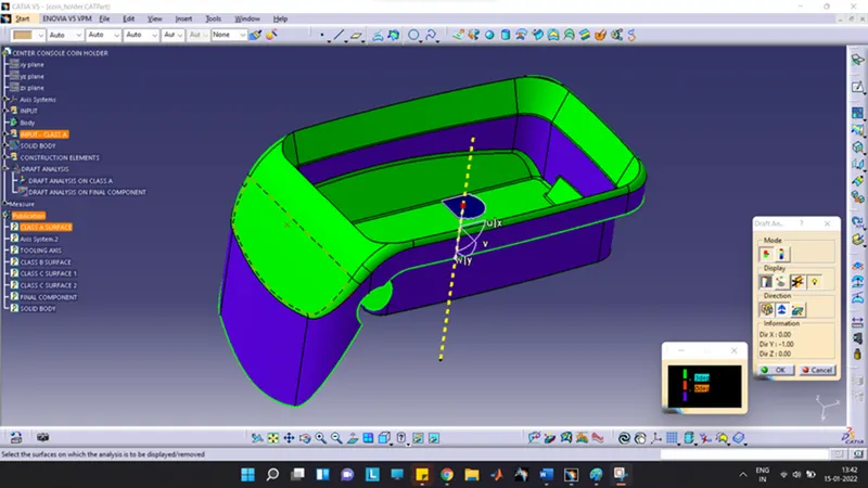
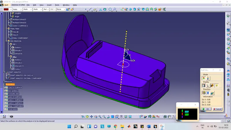
Draft analysis is used to confirm the appropriate draft angle required for the component that is to be manufactured. Quick analysis mode, show or hide color scale, and analysis under the running point are the three main features used in the draft analysis. The color scale shows the draft angle for different colored areas and the analysis under the running point shows the draft angle at different points.
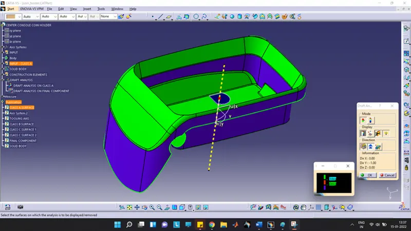
figure 24: - show or hide the color scale
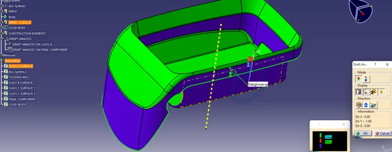
figure 25: - Analysis under the running point
Satisfaction of Rules: -
The nominal wall thickness (t) of the coin holder is 2.5 mm.
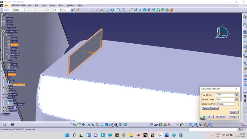
Rule1: - Rib thickness
Since the nominal wall thickness (t) of the coin holder is 2.5 mm, the rib thickness will be 0.4*t i.e 0.4*2.5 = 1 mm as shown in the below figure.
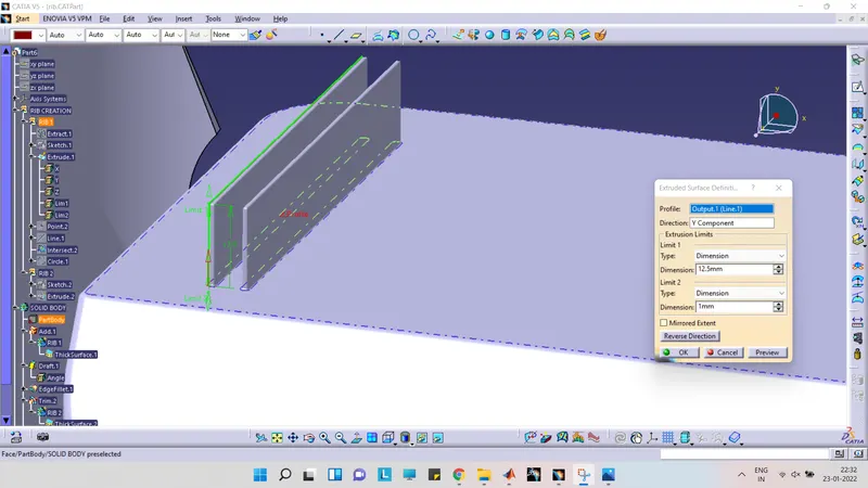
Rule2: - Rib depth
Since the nominal wall thickness of the coin holder is 2.5 mm. Hence, rib depth or height will be ≤ 5*t i.e 5*2.5 = 12.5 mm as shown in the below figure.
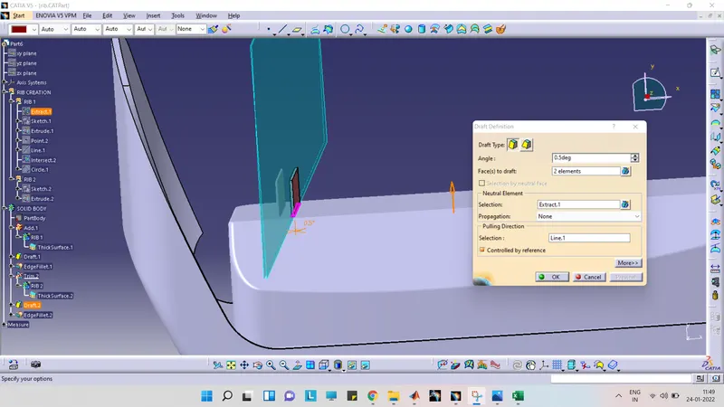
Rule3: - Rib draft
Since the draft on ribs should be ≥ 0.5 degrees. Hence, the draft given on ribs created on the coin holder is 0.5 mm as shown in the below figure.
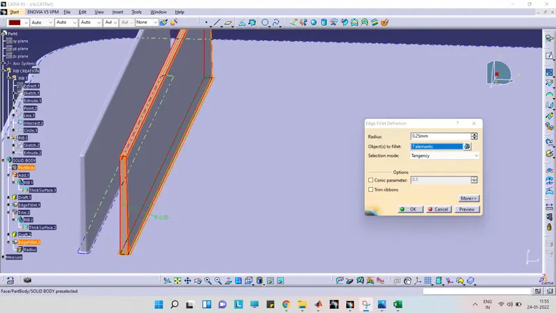
Rule4: - Rib fillet radius
In order to prevent the violation of 40% of the wall thickness requirement, the rib fillet radius selected is 0.25 mm which is the maximum one as shown in the below figure.
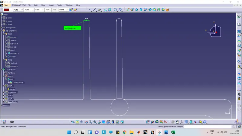
Rule5: - Rib tip thickness
The rule is that the thickness at the rib tip should be ≥ 0.75 mm. Since we got 0.786 mm as our rib tip thickness as shown in the below figure. Hence, we satisfied the given rule.
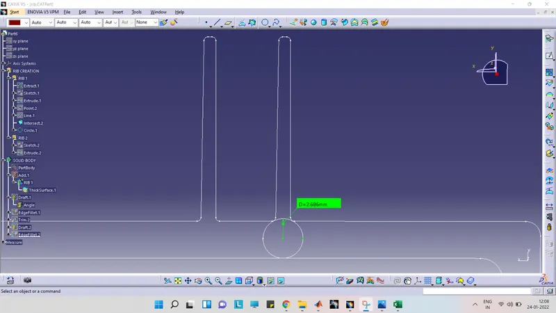
Rule6: - Rib root thickness
The rule is that the thickness of the rib root should be ±30% from the wall thickness. The wall thickness of the coin holder is 2.5 mm then the rib root thickness will be ranging between 1.75 - 3.25 mm. Since we got 2.686 mm as our rib root thickness as shown in the below figure. Hence, we satisfied the given rule.
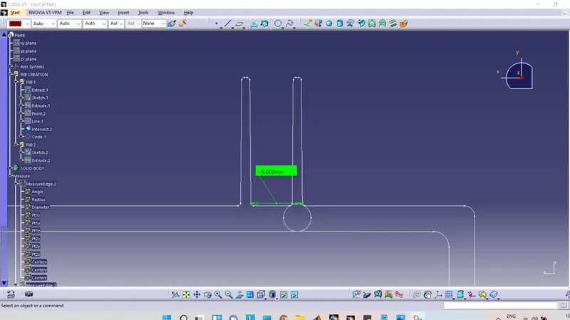
Rule7: - Spacing between two ribs
Since Ribs should be spaced so that the steel between the ribs is at a height /width ratio which is 3:1 for steel and 2:1 is preferred and the height we got in the case of coil coin holder is 12.5mm. Hence, the spacing between the two ribs is 12.5/3 = 4.16 mm and for the safe side, we kept it 5 mm as shown in the below figure.
 .
.
Screenshots of the Draft analysis report: -
- Screenshots of the Draft analysis report for Class-A surface: -
- Image of the complete Draft analysis: -
2. Images of the color scale variant: -
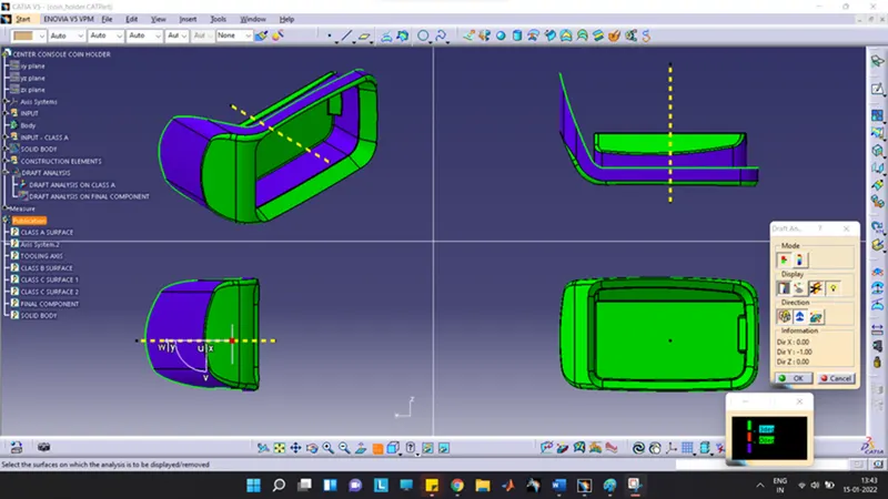
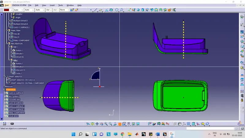
3. A model with the proper color code of the draft angle in various orientations (Isometric, Front, Side, and Top View): -
- Screenshots of the Draft analysis report for the final plastic component(with ribs): -
- Image of the complete Draft analysis: -
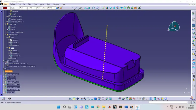
2. Images of the color scale variant: -
3. A model with the proper color code of the draft angle in various orientations (Isometric, Front, Side, and Top View): -
Other images: -
- Final component with ribs
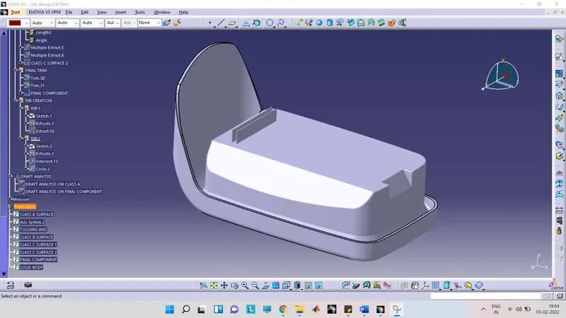
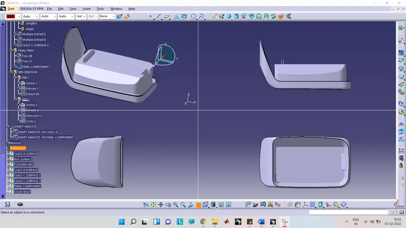
- Screenshots of the completed design in various orientations (Isometric, Front, Side, and Top View)
 .
.
Conclusion: -
- Ribs can effectively improve the rigidity and strength of plastic parts.
- Ribs should be properly structured considering the design rules to avoid mold filling problems and other defects.
- Ribs make the walls of your mold stronger without having to increase their thickness.
- The draft is important because it prevents damage from happening to the component while coming out of the mold.