Week 9 - Attachment Feature Creation - Challenge 1
RIBS CREATION: -
AIM: -
To design ribs on the coin holder considering every design rule considered in the industry.
THEORY: -
All the date required for the model to be coin holder. This data involves designing of various features. Some of the major features of the B-side are.
1.Ribs
2.screw boss design
3.Dog house design
RIBS: -
They increase the stiffness and strength without increasing overall wall thickness of the model which is not desired. They also facilitate.
1.locating and arresting components of an assembly.
2.providing alignment in mating parts.
3.Acting as stopper or guides for mechanisms.
APPROACH: -
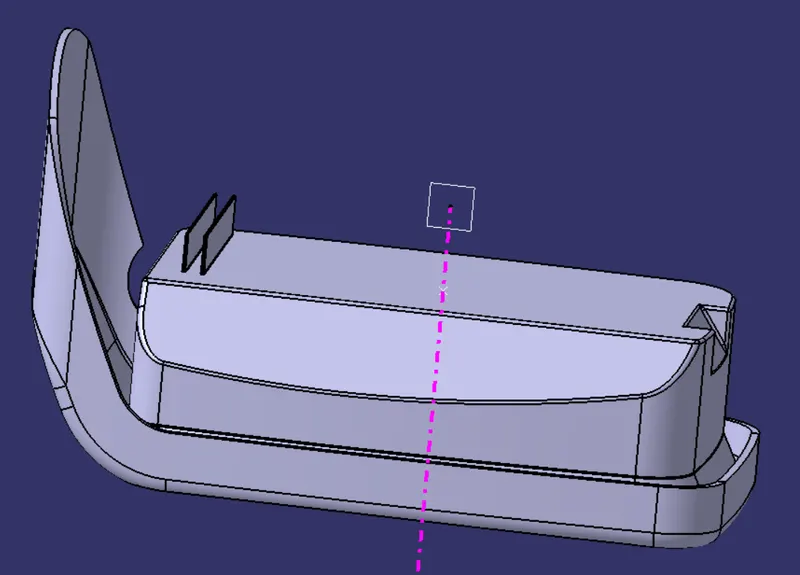
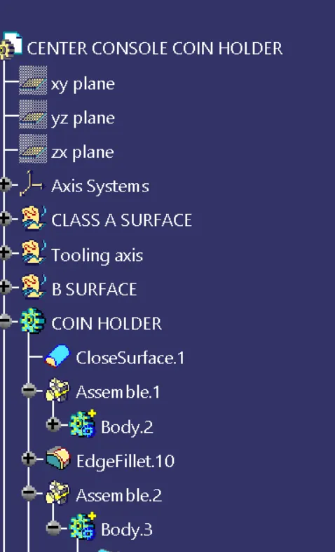
1.extract the base of the holder from outside that is form B side.
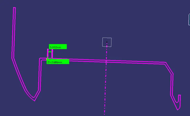
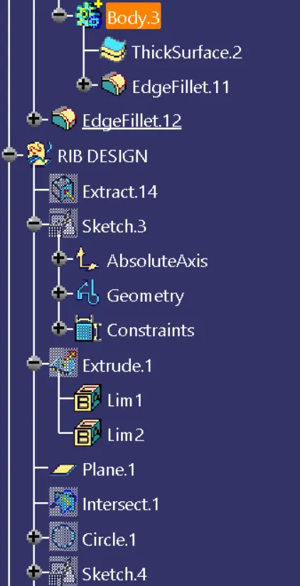
2.sketch on the x-z axis so that it seems like we are sketching on the extracted surface. We can use positioned sketch on the axis system we have created earlier.
3.extrude the sketch created. For the extrude distance we have to take design rules into consideration. That is 5*t where is the wall thickness, 2.5mm
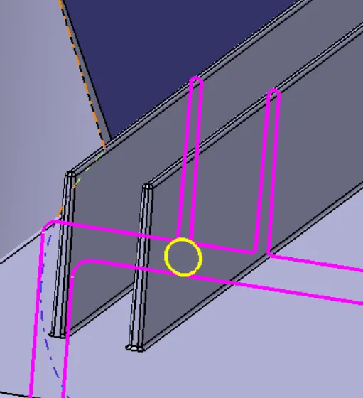
- Go to part model and thicken the extrude surface. Here also take design rules into considerations. That is 0.4*t where t is the thickness of the wall.
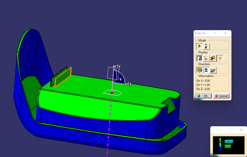
- we get a rib. Now we have to work on other features to make it fit for production. Give a draft of 0.4 deg on all the vertical faces in the direction of tooling axis.
6.Measure the tip thickness. It should be more than or equal to 0.75mm.
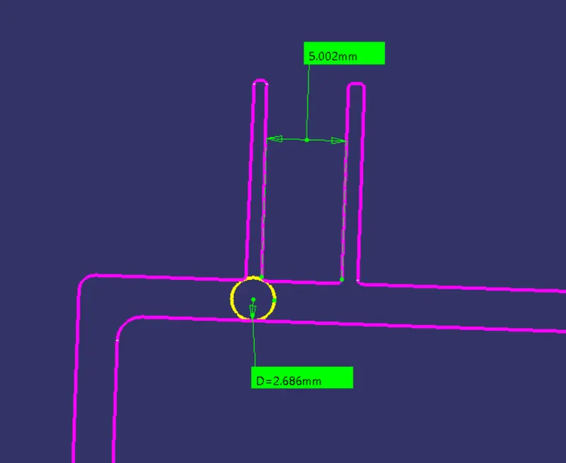
7.For two ribs make the exact same rib following the exact same procedure some distance away from the first rib. The spacing between them should be according to the rules. so we can do calculation and find spacing. One thing to note here is that, the outer face of the first rib should be that distance away from the inner face of the second rib, so while giving the distance in the sketch if we are considering first sketch as reference then we have to add thickness inn that calculation.
8.rib root thickness should be within the limits. Let us see it in detail.
9.first intersect the model with the plane of the axis system.
10.then draw a circle choosing type as tri-tangent.
- Even though it is a circle, we can see it as few sided polygon so we can correct it form the tools.
12.Now we can measure the diameter of the circle and the wall thickness which we know is 2.5mm. the diameter should not be more or less than 30% of the wall thickness.