Week 9 - Attachment Feature Creation - Challenge 1
AIM:-
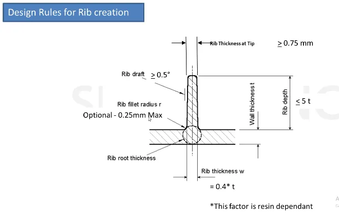
Create the rib for the Centre console coin holder considering the design rules as mentioned in the below image.
OBJECTIVE:-
- Create a Rib for the CoinHolder following Design Rules for Rib creation.
- Perform Draft analysis.
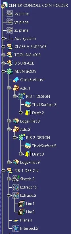
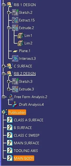
- Arrange proper tree structure.
- Geometrical sets should have a proper name based on the sketches present inside of it.
- All the sketches should be created under the Geometrical set.
RULES FOR RIB DESIGN :-
STEP-1:-
DESIGN RULES:-
- Nominal wall thickness of a plastic component: 3mm
- A deviation of +-30% from the wall thickness is accepted
- Ideal draft for a component is 3 deg
- Minimum of 0.5 deg acepted in ribs
STEP-2:-
RIB DESIGN:-
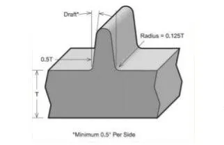
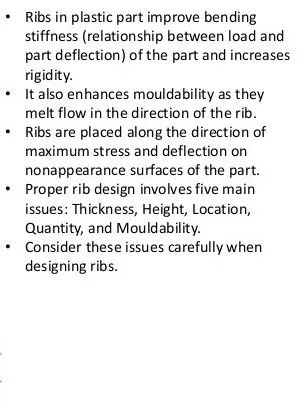
Rib provides means to economical stiffness and strength in mod parts without increasing overall wall thickness.
- Locating and arresting components of an assembly
- Providing alignment in mating parts
- Acting stops and guides for maechanisms
CREATING MORE RIBS:-
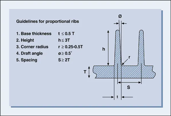
- Taller Ribs are prone to buckling under load.
- In those condition consider designing two or more shoter, thinner ribs to provide same same support with improved mold abillity
- Condition for addition rib as per the image shown below:
Guide Lines for Ribs on Show Surfaces
- Draft - 0.5 deg per side minimum
- Thickness - Base Thickness of the rib at tangent of radius(w = .4*T(wall thickness))
- Height- Depth of the Rib (<= 5T)
- Spacing - S>=2T
- Thickess at Top - Minimum thickness at Rib Tip - .75mm
- Optional Radius - .25mm maximum
Design Suggestions :-
- Do not want to signficantly increase rib thickness
- Most not violate 40%*thickness requirement
- Root Thickness can have deviation of 30% of wall thickness.
PROCEDURE :-
STEP -1:-
Sketch for the length of rib.
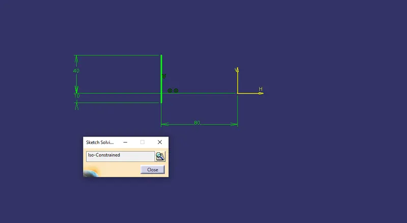
STEP -2
Extrude the sketch for 5*Thickness of the component which is (5*2.5 = 12.5mm).
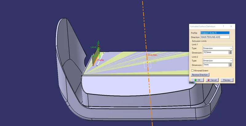
STEP -3
Thickness of the rib should be .4*Thickness of the component(.4*2.5 = 1).
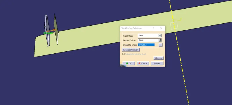
STEP - 4
Giving Draft to the Ribs from four sides of .5 deg from base.
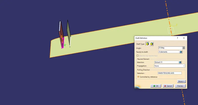
STEP - 5
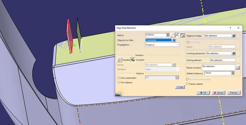
Assmeble the Rib part body inside the main part pody and then give edge fillet to all faces of rib for .25mm.
STEP - 6
Creating More Ribs
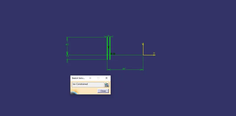
Height/Width (mm )= 3:1
12.5/Width = 3
Width = 12.5/3
Width = 4.1 ;(Width should be>3)
Here we can take 5mm for the width.
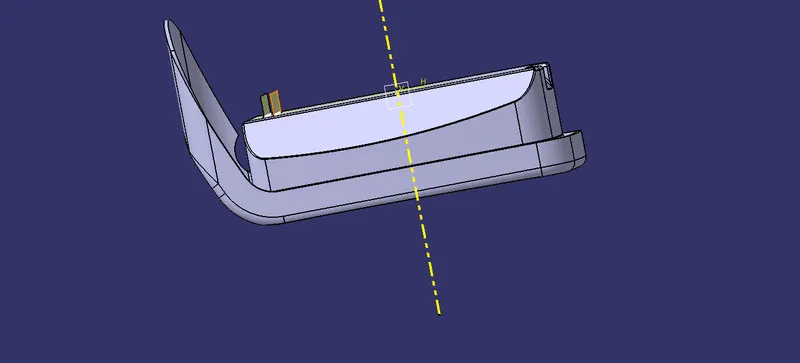
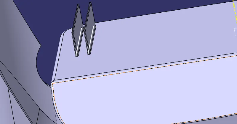
- Repeat Step 1 to Step 5 to create more ribs.
STEP - 7
Creating intersection between the reference Plane in XY Direction and component part body.
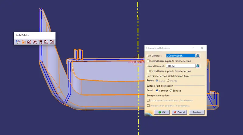
STEP - 8
Checking for proper measurments according to the design rules.
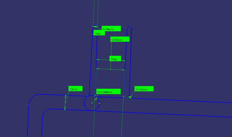
PROCEDURE FOR DRAFT ANALYSIS :-
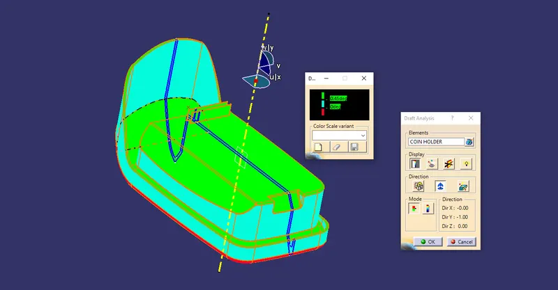
- Changing view mode to material mode in Mesh.
- Toolbar>Insert>Analysis>Feature Draft Analysis
- Drag the compass from dialogue boc to the Tooling axis and place propely.
- Click anywhere in the component and click ok.
- Analysis the colour of failing and passing surfaces.
- Gren colour means draft is upto the desired and component is ready for maufacture
- Blue means zero deg and red means below zero deg(Because of reverse direction).
TREE STRUCTURE :-
CONCLUSION
Creation of Rib on Coin Holder has been successfully done by following all the design rules and the Tooling axis has been created following OEM standards.