Week 9 - Attachment Feature Creation - Challenge 1
REPORT
AIM:
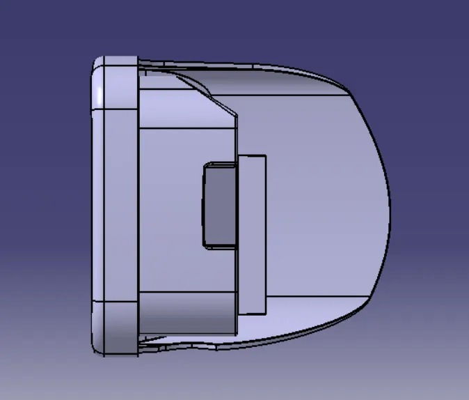
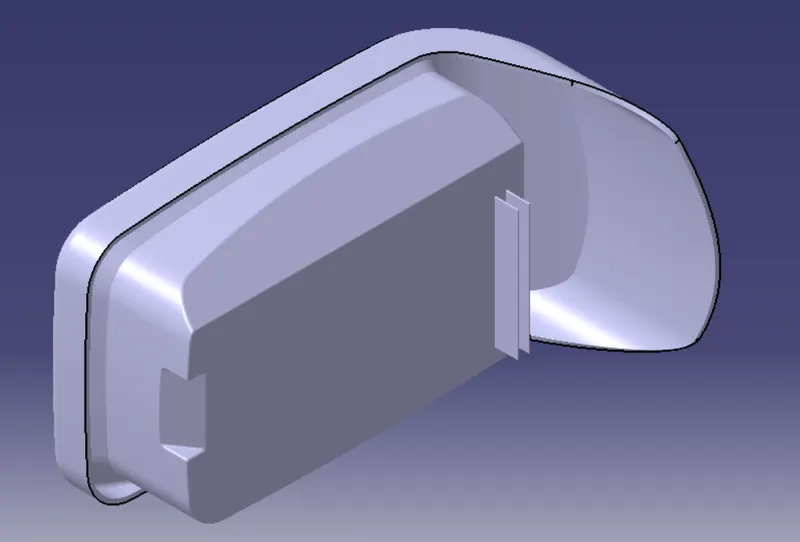
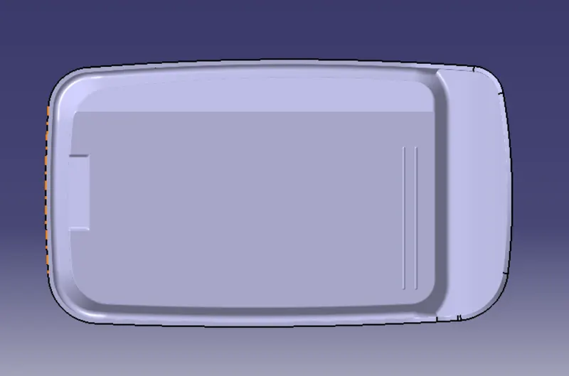
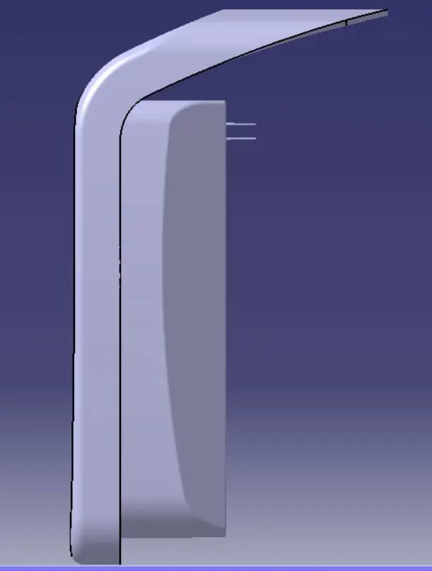
Create thr rib for the the center console coin holder considering the design rules as mentioned.
OBJECTIVE:
1. Create a rib for the coinholder following design rules for rib creation.
2. Perform draft analysis.
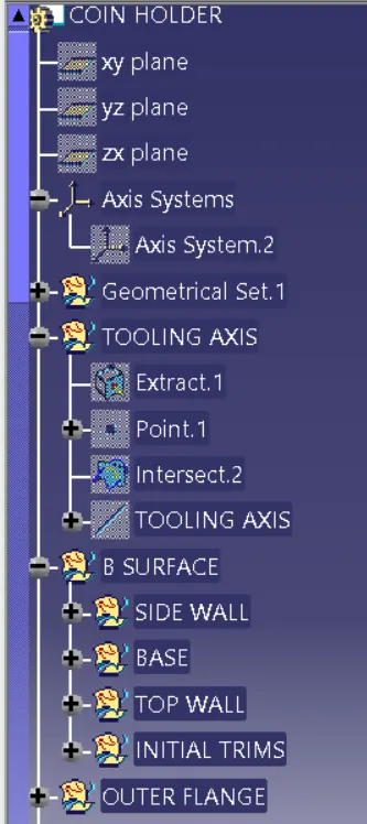
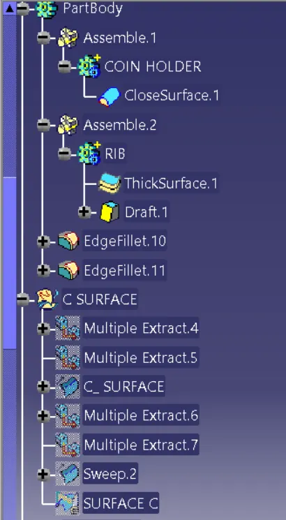
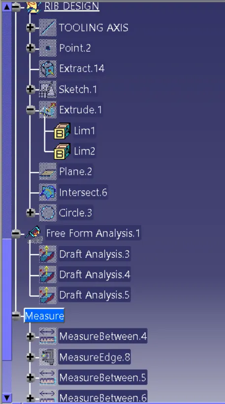
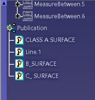
3. Arrange proper tree structure.
4. Geometrical sets should have a proper name based on the sketches present inside in it.
5. All the sketches should be created under the geometrical set.
RULES FOR RIB DESIGN:
DESIGN RULES
1. Nominal wall thickness of a plastic component is 3mm.
2. A deviation of +-30% from the wall thickness is accepted
3. Ideal draft for a component is 3 deg
4. Minimum of 0.5 deg accepted fro ribs
RIB DESIGN
Rib provides means to economical stiffness and strength in mold parts with out increasing overall wall thickness.
1. Locating and arresting components of an assembly
2. Providing alignment in mating parts
3. Acting stops and guides for mechanisms.
CREATING MORE RIBS
1. Taller ribs are prone to buckling under load
2. In those condition consider designing two or more shooter , thinner ribs to provide same support with improved mold abolity
3. Condition for addition rib as per the image shown below.
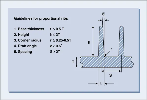
Guid lines for Ribs on show surfaces
1. Draft - 0.5 deg per side minimum
2. Thickness - Base thickness of the rib at tangent of radius(W=0.4*T(Wall thickness))
3. Height - Depth of the Rib (<= 5T)
4. Spacing - S>= 2T
5. Thickness at Top - Minimum thickness at the rib tip - 0.75mm
6. optional radius - 0.25mm maxiumum
Design suggestions -
1.Do not want to signficantly increase rib thickness
2. Most not violate 40% thickness requirement
3. Root Thickness can have deviation of 30% of wall thickness.
PROCEDURE:
1. sketch the length of the rib.
2. Extrude the sketch for 5* Thickness of the component which is (5*2.5= 12.5mm)
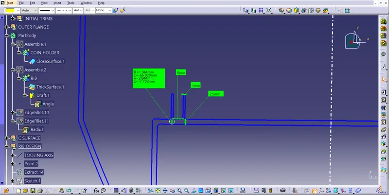
3. Thickness of the rib should be 0.4*thickness of the component(0.4*2.5=1mm)
4. Giving draft to the Ribs from the four sides of 0.5 deg from base.
5. Assmeble the rib part body inside the main part body and then give fillet to all faces of rib for 0.25mm.
6. Creating more ribs
Heigt/width= 3:1
12.5/ width= 3
width= 12.5/3
width= 4.1( width should be greaterthen 3)
Here we can take 5mm for the width.
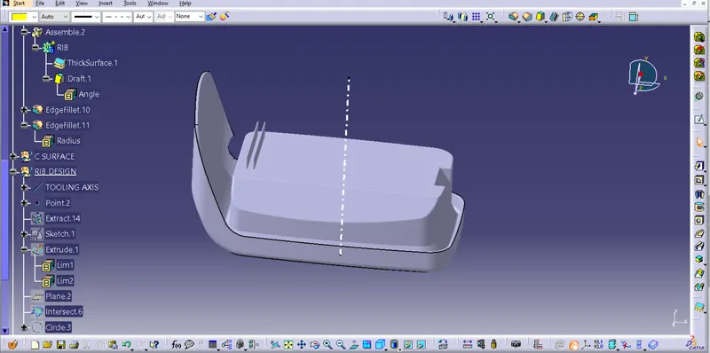
7.Creating intersection between the reference plane in XY Direction and component part body.
8. Checking For proper measurments according to the design rules.
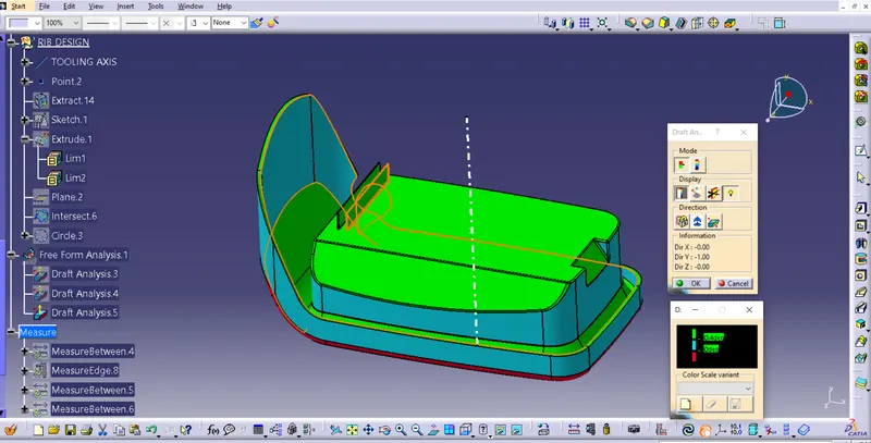
PROCEDURE FOR DRAFT ANALYSIS:
1.Changing view mode to material mode in mesh.
2.Toolbar> insert> analsysis > feature draft analysis
3. Drag the compass from dialogue box to the tooling axis and place properly.
4. Click anywhere in the component and click ok.
5. Analysis the colour of failing and passing surfaces.
6. Green colour means draft is upto desired and component is ready for manufacture.
7. Blue means zero to .5deg and red means below zero deg ( because of reverse dierction).
CONCLUTOON:
Creation of rib on coin holder has been successfully done by following all design rules and the tooling axis has been created following OEM standards.
FEATURE TREE: