Week 9 - Attachment Feature Creation - Challenge 1
AIM :DESIGN OF RIBS USING CENTRE CONSOLE COIN HOLDER
DESCRIPTION : DESIGN OF RIBS ,TOOLING AXIS WITH BYSECTION METHOD & PERFORM DRAFT ANALYSIS ON WHOLE PART,.
To make the part to an angle dirtection. so that the part model can be easily removed from the model cavity-core.
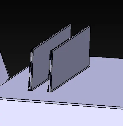
RIBS Ribs acts as the stiffiness to the component gives strength to it .to create the ribs on the bottom of the coin holder using the design rules to be followed.
extract the surface create the point on surface as referance & create the line
create the positioned sketch draw the line on the surface make it iso constrained by giving the dimensions.
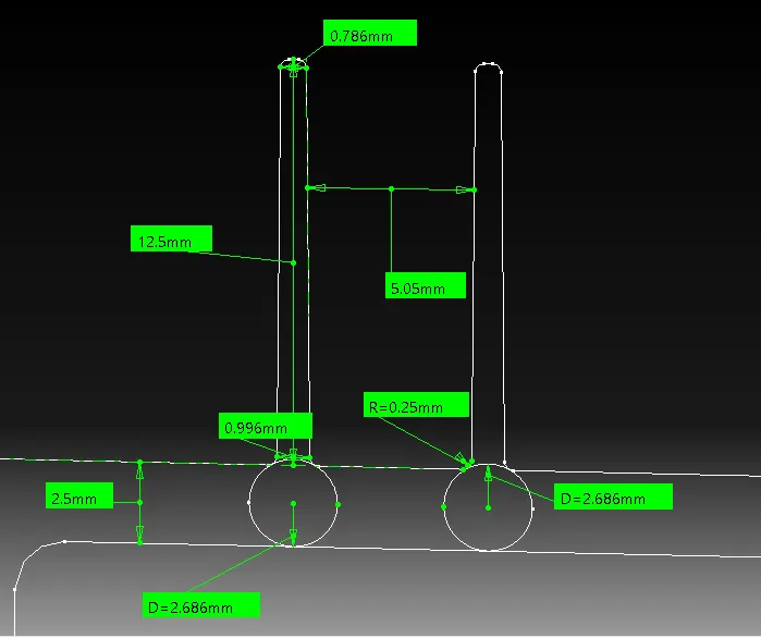
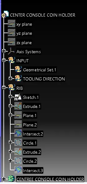
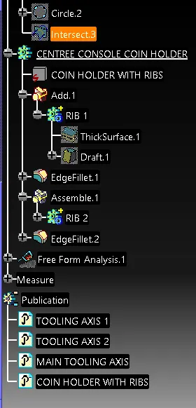
create the extrude using extrude command with tooling axis referance with 12.5 mm i,e. (2.5*5mm) (thickness of component* 5 times = 12.5mm) depth upward direction & 1mm toward downward so the it can add tothe part model without no errors.
inser the body define it and thick the surface of 1mm i,e.(2.5*0.4)( thickness of component *0.4 times 2.5*0.4= 1mm)
DRAFT ANGLE the draft to be used to the ribs as per the design rule is .05mm
FILLET RADIUS -0.25 AS PER DESIGN RULES.
RIB ROOT THICKNESS should be not > than 3 mm max.
SPACING The gap between the two ribs is 3:1 i,e (depth of rib /thickness of part 12.5/3=5)
Ribs are design on the coin holder following the design rules are attached below with measurements.
DRAFT ANALYSIS
IT is a analysis of a plastic component to determine weather the component is actually feasible to manufacture or not mainly used for thicken the surface.at certain angle (3deg)
REQUIREMENT FOR DRAFT ANALYSIS
solid body
main tooling direction
select material mode
TOOLING AXIS CREATION
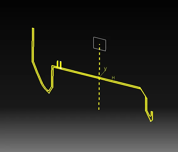
Check the correct direction & extract the required surface & create the line with point direction.highlet it so that it can be easily visible .(tooling axis 1) y direction
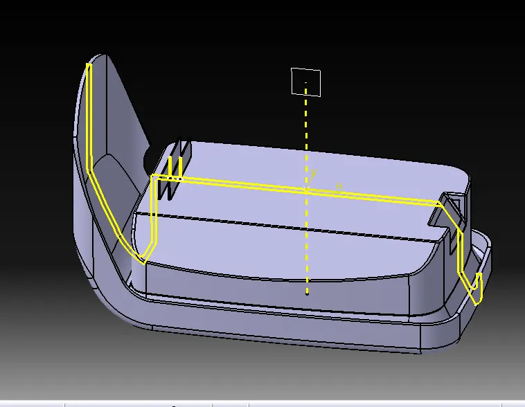
check the x direction create the plane & interect teh part & sketch the point to point lines as referance & create the bysection line name it as (tooling axis 2)
by the above two lines create the main tooling axis with bysecting method the obtained line required tooling axis so that the draft analysis can be performed clearly on the whole part.including ribs.
to clear the draft analysis even the ribs side core is used
TOOLING AXIS BYSECTION METHOD .The tooling axis is created only in bisection methiod because the draft analysis should perform clearly with 3 deg on the required direction .it is created by choosing the clearance of complete part and then the tooling axis is created.the part is intersected and the point to point lines are created by the two line the bysection line is created.that is the actual tooling axis.
STEPS FOR DRAFT ANALYSIS
- switch to material mode
- activate feature draft analysis
- place the compass on main tooling direction
- activate compass logo 7 slightly move the compass over MTD line.
- set the angle & colour as per the requirement
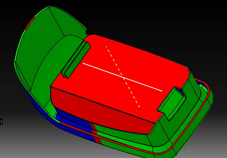
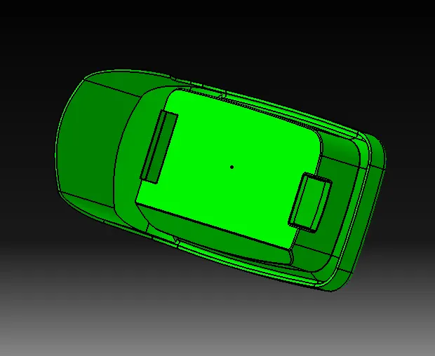
GREEN- area clear in main tooling
RED- area have no draft in main tooling
BLUE- area undercut in main tooling
- click on bodu on which draft analysis to be done
- ckeck a surface feasibility.
TYPES OF DRAFT ANALYSIS
catia v5 has two types of draft analysis
1. Quick analysis
2. Full analysis
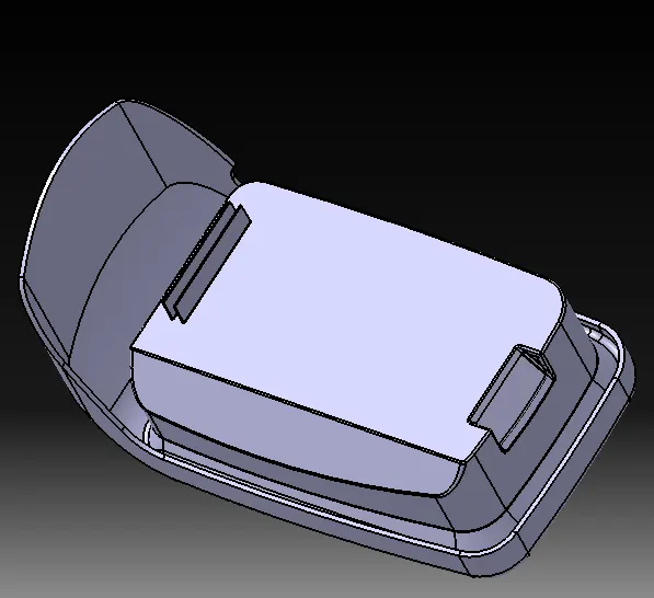
DRAFT ANALYSIS- it is performed on the centre console coin holder using the tooling axis is clear.
TOOLING AXIS- it is used to perform the draft analysis to apply the compass on it to perform the draft analysis.
RESULT the ribs are design using the design rules , draft analysis is performed on the whole part .images is shown below