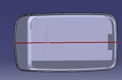
Week 9 - Attachment Feature Creation - Challenge 1
Objective
- To mention what is draft analysis
- To mention what is tooling axis
- To mention the steps to create tooling axis
Draft Analysis & Tooling axis
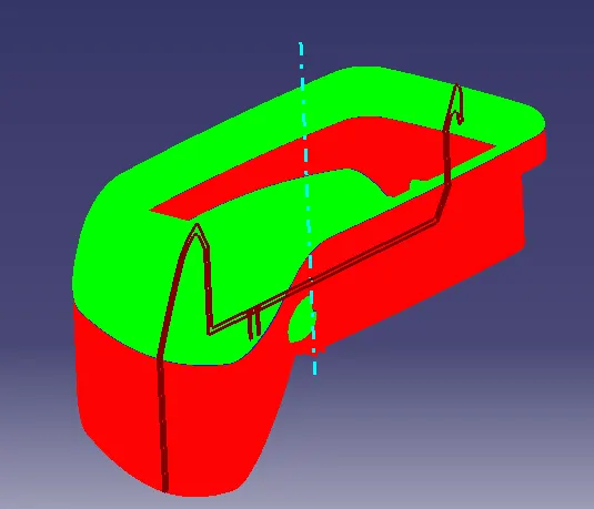
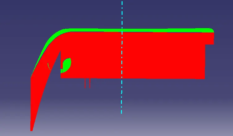
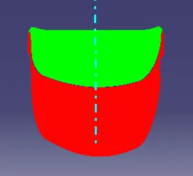
This is the analysis which is used to check weather the draft of certain plastic design or material is possible or not. The main requiement for this analysis is Tooling axis for the given plastic component and Class A surface of the component. Tooling axis is the asix which is created by plastic designer which is going to be used as Tooling axis for injection moulding which is the axis were both core and cavity get seperated in most condition tooling axis is created in the place where the component has cenetr hole or on the center surface of the component. Tooling axis is created in center in such a way that all the drafted surface of component measured same draft angle with respective X axis and Y axis. Creation of Tooling axis is different for different component here we used Bisecting method. After creation of tooling axis draft analysis is done the axis is dragged and kept over tooling axis and got locked and direction of draft analysis is given and draft degree is given in scale mostly 3 degree is given. If all surface of component are able to pass 3 degree all surface will be coloured in green. If any surface cannot pass 3 degree to 0 degree it is coloured in blue and if any surface below 0 degree it will be coloured in red colour. Using Cone tool we can measure the angle of the surface.
Creation of Tooling axis:
- The center surface is extracted
- Then the point is created on the center of the surface
- The line created on the point which is called as tooling axis
- The tooling axis line is thicken and changed to blue colour
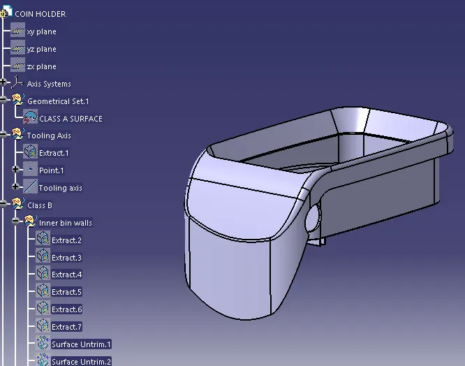
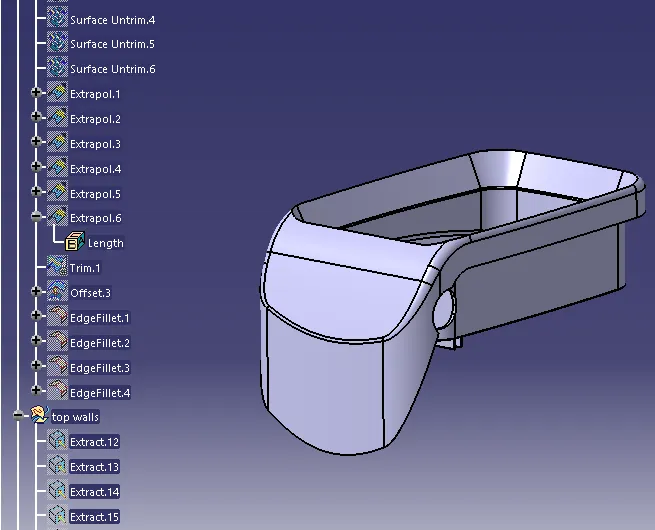
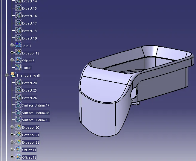
Total Tree structure
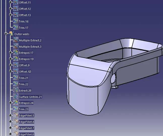
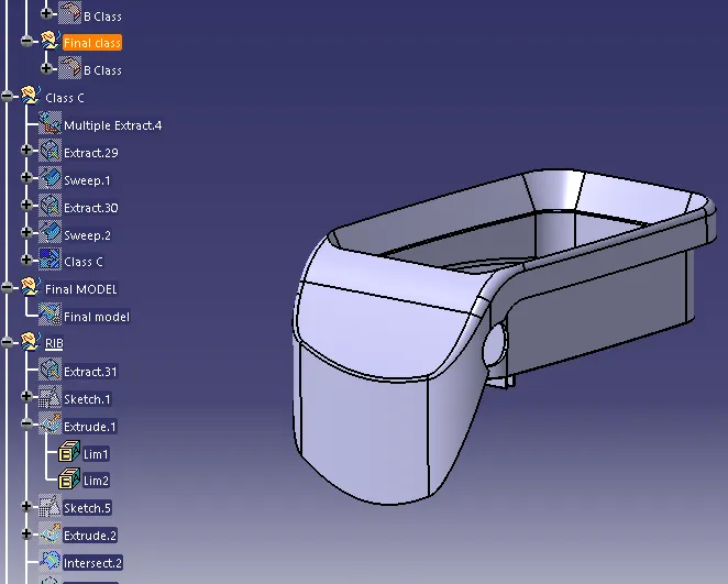
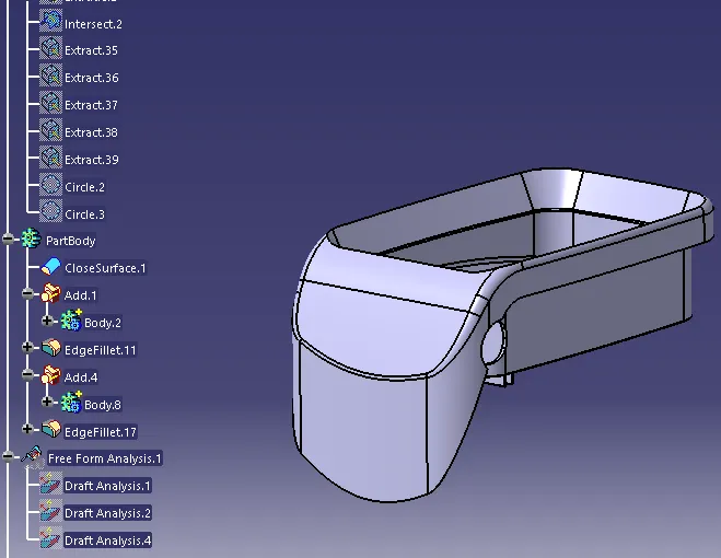
Rib creation
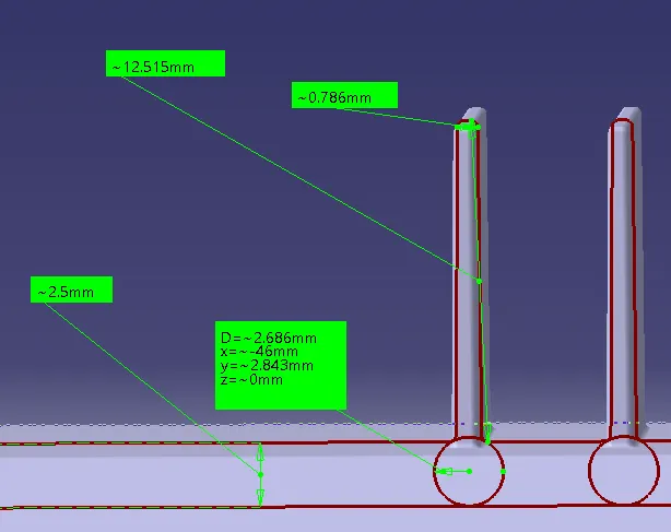
The bottom B surface in extracted then the sketch for rib is created ovr the surface and it got extruded to the height 5 * T ( T - tickness of coin holder) . Then the thickness is given for the surface extruded and it is made in to solid and faces are drafted and filleted the value for all above mentioned steps is given as per design rule of rib once one rib is created the same procedure is followed for second rib and then intersect is taken for whole component and design rule for rib is checked and finally draft analysis is done for whole component.
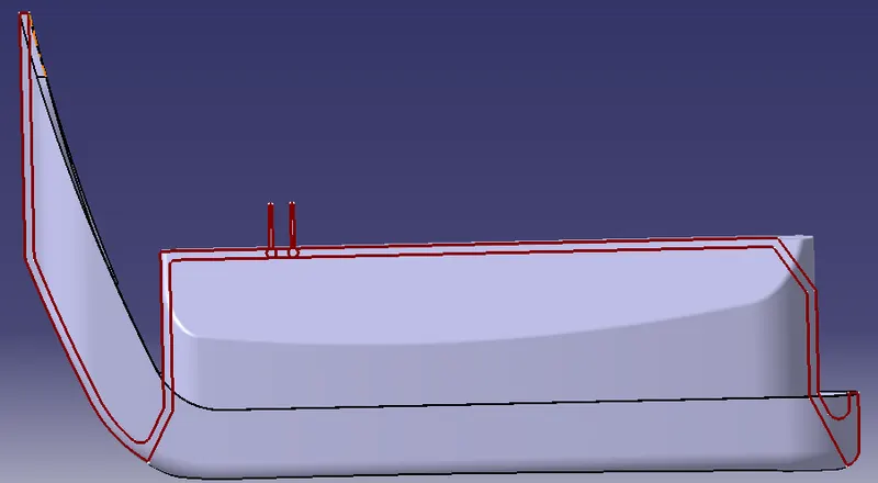
Checking as per deign rule
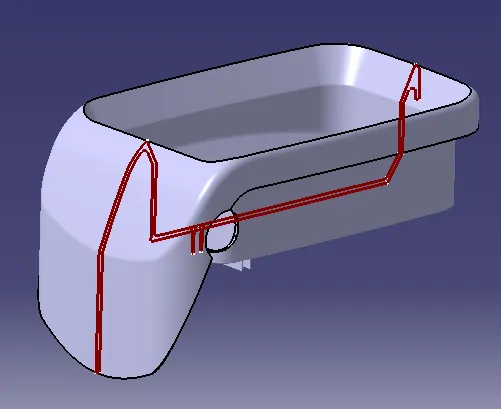
Isometric view
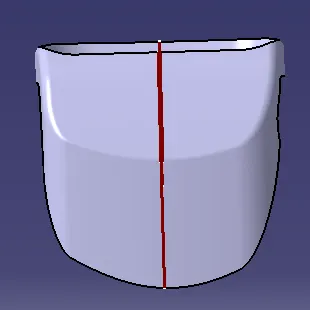
front view
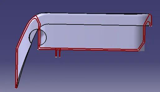
side view
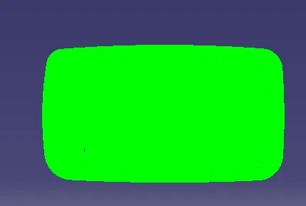
bottom view