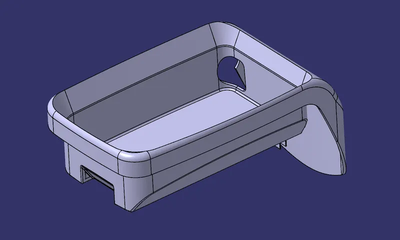
Coin Holder Rib Design
COIN HOLDER RIB DESIGN
Rib Design:
- In order to design the rib on the bottom part of the given component, we start by taking the bottom surface extract. Take a point on the surface center and a plane through this point and parallel to YZ plane.
- Now, take a positioned sketch on the XZ plane (along bottom surface) and draw a line as shown below.
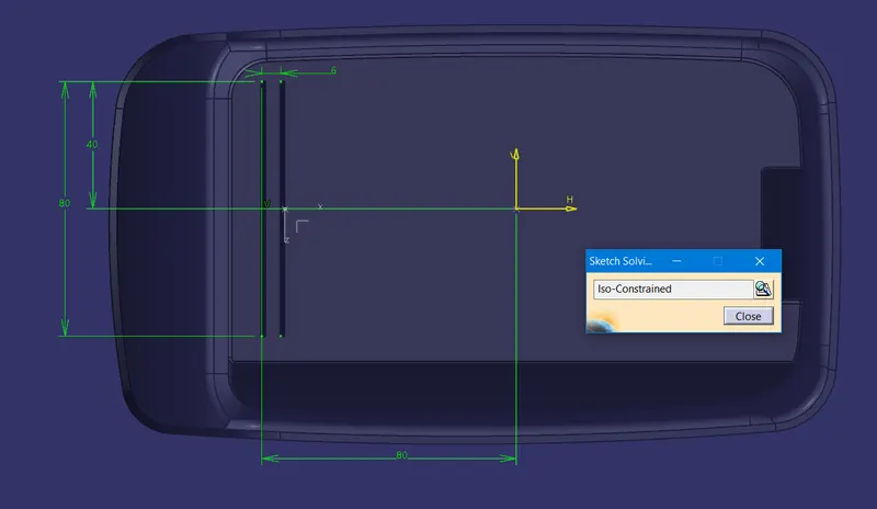
- Extrude the line along tooling axis direction by appropriate length. This will be the rib height. Including the draft, the rib height can be up to 5 times the normal wall thickness.
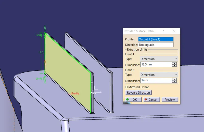
- It is necessary to provide all the ribs along the tooling axis direction as they will need to be easily released from the mold.
- Thicken the surface by appropriate thickness value. The rib thickness can be 0.4 or 0.5 times the component thickness. Minimum rib thickness at tip can be 0.75 mm.
- Now we need to provide draft to all vertical walls of the rib. The draft angle should be at least 0.5 degrees on each side.
- Now we can apply fillets to the edges of the rib.
- Now for the second rib, we need the distance between 2 ribs. The distance between 2 ribs should be 2 times the normal body thickness. Hence, as the normal body thickness is 2.5 mm, the distance between the 2 ribs can be taken 5 mm.
- But the rib will be thickened in other direction so we have to take 6 mm as the offset distance. For the second rib we need to edit the sketch and offset the first rib line by this distance.
- Then by repeating the previous steps, extrude the line, thicken and fillet the edges with corresponding similar dimensions.
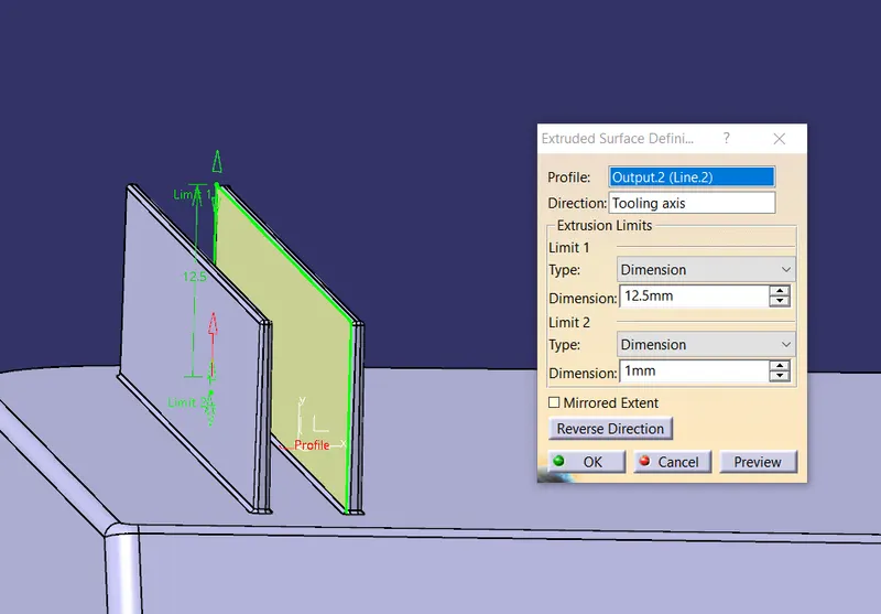
Rib Root Thickness Analysis:
- For rib root thickness analysis, take intersection between solid body and the preciously created plane parallel to XY plane as shown below.
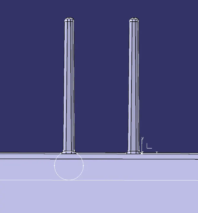
- Then along the plane of intersection, take a tritangent circle such that it is tangent to the bottom line and to the fillet curves as shown below.
- Then consider the following dimensions and check for correct dimension values.
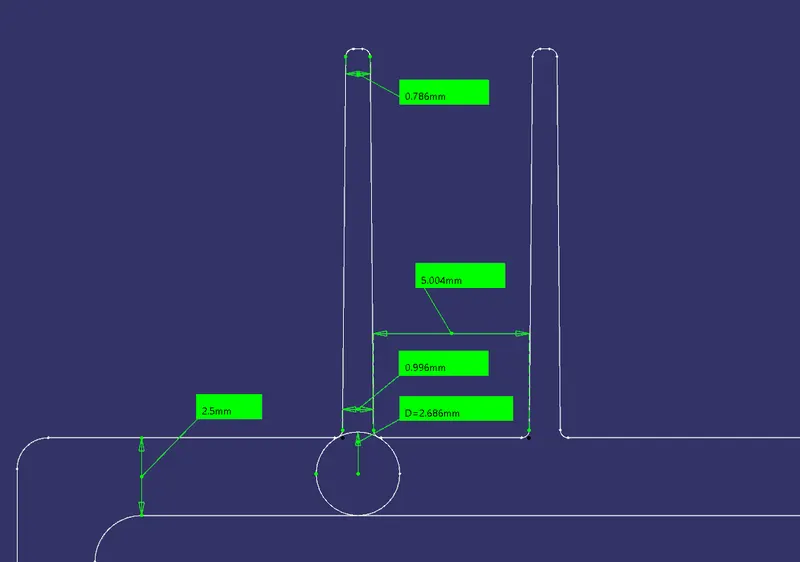
- The ratio of rib height to distance between the 2 ribs should be 3:1. In our case, rib height is 12.5 mm and from above image, distance between the ribs is 5 mm. Thus, the ratio comes out to be 2.5 which is acceptable.
IMAGES
DRAFT ANALYSIS AND COLOR SCALE VARIANT (WITHOUT RIB)
Class A Surface
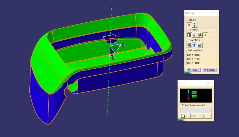
Solid Body
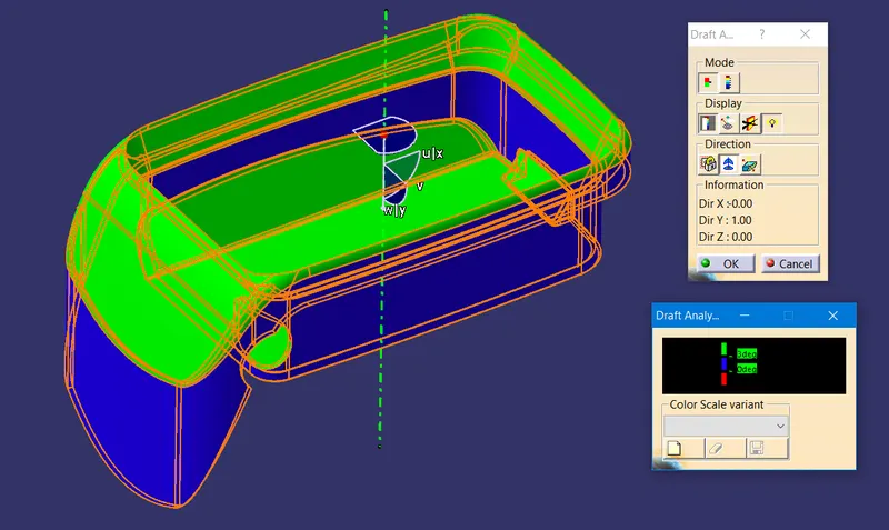
Draft Analysis of final component with Rib:
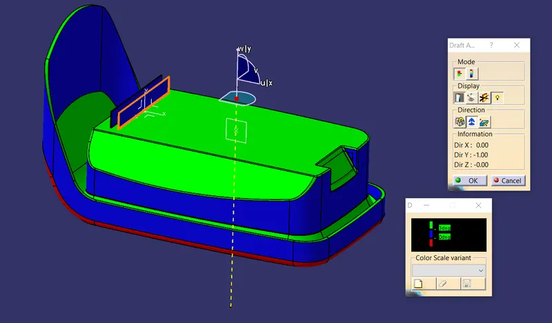
Blue colour indicates that the ribs are along the tooling axis.
Model different views
Surface Body (Without Ribs)
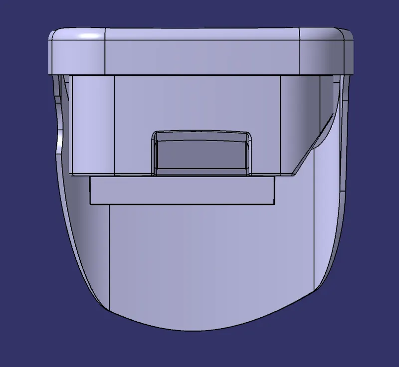
Front view
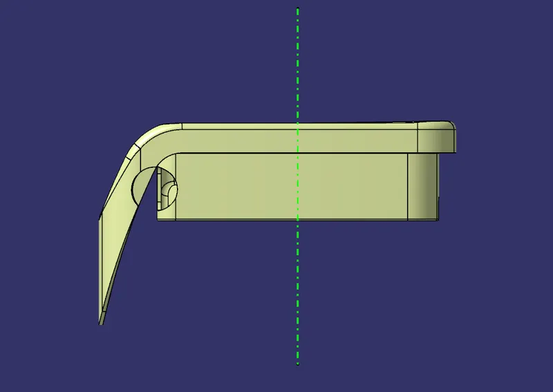
Side view
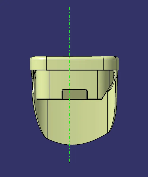
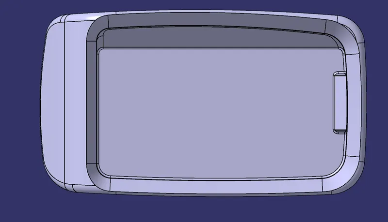
Top view
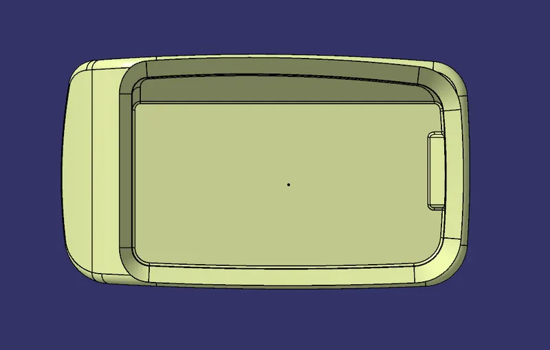
Isometric view
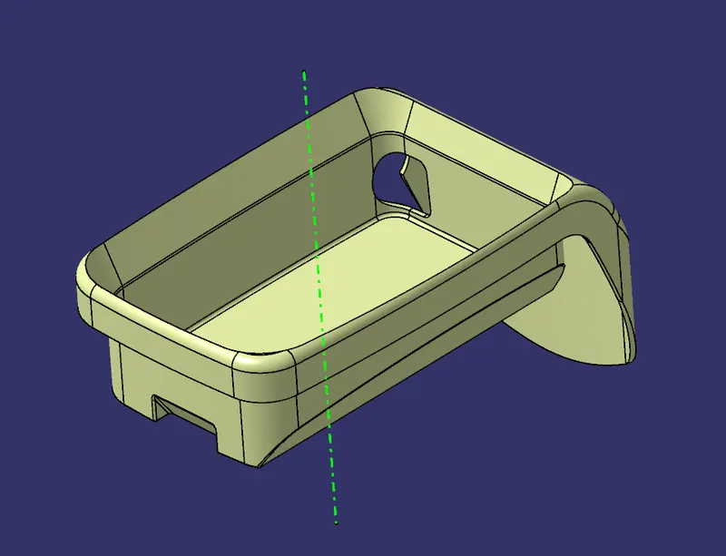
Solid Body (With Ribs)
Front view
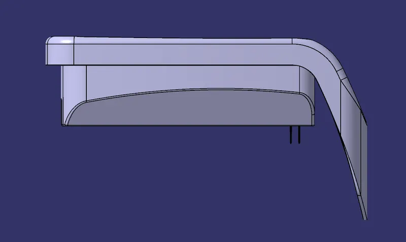
Side view
Top view
Isometric view